I suggest that you use these:-
https://www.digikey.co.uk/product-detail/en/talema-group-llc/62051/1295-1073-ND/3881358
You will need to mount them somewhere else, maybe on the metalwork, but they only need one mounting bolt each. Toroidal transformers usually come with a round metal plate, two round foam pads and a bolt. The bolt clamps the transformer between the metal plate and a flat metal surface that needs to have a hole drilled for the bolt. The foam pads go between the transformer and the metal to even out the pressure.
The transformers I suggested are 9 V, not 10 V, but that probably doesn't matter. A transformer is at its rated voltage at full load, so the original transformers would have been a bit above 10 V, probably nearly 12 V, with no load, dropping to 10 V at full load. The replacements that I've suggested are larger and have a higher rating, so they won't drop as much, and they start at 10.5 V with no load.
Also, you can add a few turns to a toroidal transformer quite easily by just threading ordinary wire through the hole in the centre and around the outside. Each pass through will add about 1/8 V for that size of transformer, so adding 1 Volt isn't a big deal. There's a short thread here
https://www.electro-tech-online.com/threads/kef-psw2500-active-base-unit-repair.159244/ about adding a second winding to a transformer. To add voltage, you just put a few turns in series with the existing windings. If the voltage goes down not up, reverse the direction of the additional windings.
The suggested transformer has dual primary winding and dual secondary windings. You have to connect it correctly and as it has wires not pins, you have to be methodical. The schematic of the transformer is on page 8 of the data sheet
https://talema.com/wp-content/uploads/datasheets/Transformer-Catalog.pdf
To connect the primary windings to 120 V you connect the live wire to brown and grey, and you connect the neutral to blue and violet.
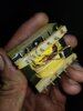
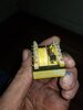
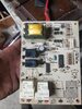
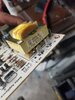
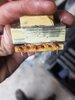
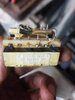
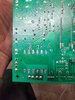
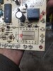
On the secondaries, the two circuit diagrams are different. One shows the windings connected in series, and the other shows them as separate windings. The transformer that you have has a few spare pins so it's not clear which ones are actually used. If you post a picture of the circuit board that show the tracks, we can probably tell you how to connect up the secondaries.