Continue to Site

Welcome to our site!

Electro Tech is an online community (with over 170,000 members) who enjoy talking about and building electronic circuits, projects and gadgets. To participate you need to register. Registration is free. Click here to register now.

  • Welcome to our site! Electro Tech is an online community (with over 170,000 members) who enjoy talking about and building electronic circuits, projects and gadgets. To participate you need to register. Registration is free. Click here to register now.

Tone Generator

Status
Not open for further replies.
The max output high voltage of the 555 is only 4V and the minimum voltage is 2V.

With only 2V across it an 8 ohm speaker gets only 125mW for a sine-wave or only 0.25W for a square-wave.
No that's a worst case scenario when driving a load of 200mA.

In reality the saturation voltage won't as high. The load seen by the 555 will be the beta of the transistors multiplied by the emitter load.


For 2.25W an 8 ohm speaker needs 12V p-p and a 555 cannot supply enough current. The amplifier needs a 14V to 16V supply.
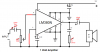
No, I was talking about the single ended driver I posted previously.
https://www.electro-tech-online.com/attachments/tone-gen-gif.32336/

The saturation voltage of the transistor is negligible, if the P = 6²/8 = 4.5W but the duty cycle will be about 50% so that becomes 2.25W like I said.
 
Last edited:
Without anything to limit the base current of the transistor then the 555 and transistor will both curl up and die.
 
Yes, you're right, you need a 68Ω base resistor.
 

Attachments

  • Tone gen.GIF
    Tone gen.GIF
    19 KB · Views: 265
I don't see why not. There are 1000s of commercial products which drive small speakers in this manner and all they work.

True, if this were an audio amplifier the speaker would clip sooner but it's not, it's just a simple buzzer so it doesn't matter.
 
Thanks again for the replies,

Hero999

The idea of the IC is more for learning.
I am using the circuit as a learning tool of sorts, i will try some of the suggestions, thanks for posting some schematics.

Although, i would like the sound to be more than just a Beep, i am trying to create a completely smooth tone more like a continuous musical note rather than a Buzz or a Beep that changes when triggered.

It makes it more difficult i realise but for learning i find it very interesting.


audioguru

I see what your saying about the LM380 as a bridge amplifier, i didn't look close enough & assumed it was a dual IC.
Yes the data sheets for the TDA2822M (8-pins case), is what i have.

I have some LM833 IC's that i discovered & also some LM324N 14pin that i could use.

I also found an 8 0hm 3 Watt max speaker so i can use this.
I am just trying to use what i have at hand at this stage.

I have drawn a rough schematic using the LM380 which i have attached, if this is suitable for the 8 ohm 3W speaker can i also add a Tone Control using an IC. I have attached a Tone control schematic as well, this one using a LM833.

If i can use it, how to connect it correctly to the LM380 circuit attached?
 

Attachments

  • LM380N-Amp.gif
    LM380N-Amp.gif
    8.9 KB · Views: 1,332
  • Tone.gif
    Tone.gif
    11.3 KB · Views: 548
Last edited:
If you want a smooth sound then you need a sine rather than a square wave.
 
I corrected your LM380 1W amplifier.

The LM833 tone control circuit has one input grounded so it needs a dual polarity supply. It must be fed from a very low impedance like the output of an opamp.
 

Attachments

  • LM380 1W amplifier.PNG
    LM380 1W amplifier.PNG
    19.2 KB · Views: 476
Have you considered a Wein bridge oscillator?

Look at page 5 of the LM386 datasheet. You should be able to apply this to the LM380 or similar amplifier.

I hope you know that a tone control won't alter the frequency, it'll just alter the loudness of different frequencies so I don't see the point unless this is an educational exercise.

To alter the frequency you need to alter the RC constant of the oscillator. The 555 can be adjusted by varying one resistor but the Wein bridge requires two variable resistors so you need a dual ganged pot.

https://www.electro-tech-online.com/custompdfs/2009/08/LM386-1.pdf
 
audioguru,
Thank You for sorting out the amplifier schematic for me, much appreciated:D.

I understand what you say with the tone control circuit.
I need to breadboard a few things now to sort it all out.

Thanks Again!


Hero999,

Yes i worked out that a sinewave was needed as the 555 timer output certainly has a frequency beat to it.

No i hadn't considered a wienbridge oscillator, i am now that you mentioned it.

I understand about the tone control, i may need it to change the Bass tone so the speaker doesn't sound to cheap, maybe.

Is the wienbridge circuit an amplifier as well or do i still connect the lm380 amplfier circuit that audioguru has sorted out for me after the wienbridge circuit?

On the lm386 wienbridge circuit you mention, it has a lamp in the circuit, can i just substitute a 200 Ohm resistor for this?

I will have a look & see if i can work out how to connect the LM380 the same as the LM386 for this circuit.:eek:

Just at a quick glance i am not sure how to add my signal to this circuit so i get a change in oscillation--sound.

Thank You.
 
Last edited:
The LM386 is a small amplifier so will drive a small speaker.

The lamp can't be substituted for a resistor, a lamp's resistance increases with the current flowing through it and in this case this property is relied upon to stabilise the amplitude.

There is an error in the circuit: the bottom 4k7 should be 47k.
 
Status
Not open for further replies.

Latest threads

New Articles From Microcontroller Tips

Back
Top