Continue to Site

Welcome to our site!

Electro Tech is an online community (with over 170,000 members) who enjoy talking about and building electronic circuits, projects and gadgets. To participate you need to register. Registration is free. Click here to register now.

  • Welcome to our site! Electro Tech is an online community (with over 170,000 members) who enjoy talking about and building electronic circuits, projects and gadgets. To participate you need to register. Registration is free. Click here to register now.

Timer Not in sequence

Status
Not open for further replies.

vincentspm

New Member
Hi All,

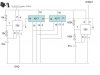
I connected 1 555 timer and 2 IC 4017 counter.
when i supply voltage by 9v DC battery, all the timing no problem,
but once i supply using 9v AC-DC adapter, the timing are not in sequence, and on randomly.

Example:
i connect 1st IC 4017 9th output to a LED, and 555 timer output to 4017 clock input.
By right it should 10 pulse from 555 timer, and 1 output pulse from 4017,
for my case, it keep random blinking on 4017 output.

Can i know why it can happpen?
 
Well, looking at your schematic... oh wait! You haven't posted one. How are we supposed to evaluate your circuit?
 
Sorry about that, here my circuit schematic
 

Attachments

  • schematic.JPG
    schematic.JPG
    52.4 KB · Views: 153
Pin 15 of each 4017 is its RESET pin that you must activate when the power is applied to the circuit. A resistor and capacitor will do it.

All electronic circuits need a supply bypass capacitor that yours does not have.
 
Pin 15 of each 4017 is its RESET pin that you must activate when the power is applied to the circuit. A resistor and capacitor will do it.

All electronic circuits need a supply bypass capacitor that yours does not have.

Thank you for your information, i will try it later.
 
You need a whole different adaptor. You might try connecting a large value electrolytic capacitor where the power connects to your project board. Use the largest capacitor you can find, but it should be at least a couple hundred micro farads. Make sure it's rated for the voltage you're using.
 
Last edited:
Pin 5 of the 555s should be connected to 0V via a 10nF capacitor.

Why are you using two 555s when all you need is a single 556?
 
Why are you using two 555s when all you need is a single 556?

Hi Hero,

I once used a 556 and two different frequencies to work with. Timer A worked as proposed 500Hz and timer B (380Hz) was way off (at about 2.5KHz). I was by no means to be corrected.

I guess there is a problem with dual timer chips when operating at different frequencies.

Boncuk
 
Hero999 i agree with you. i have stoped using 556 since i discovered this. the cirfuit above need some filter to reduse noise becuse 4017, 4013, 555 and other clock inputs respondes to noise easily.
 
I once used a 556 and two different frequencies to work with. Timer A worked as proposed 500Hz and timer B (380Hz) was way off (at about 2.5KHz). I was by no means to be corrected.

I guess there is a problem with dual timer chips when operating at different frequencies.

That's strange, I've done that before with no problems.

Were both control voltage pins connected to 0V via 10nF capacitors and the supply voltage properly bypassed with 100nF?
 
That's strange, I've done that before with no problems.

Were both control voltage pins connected to 0V via 10nF capacitors and the supply voltage properly bypassed with 100nF?

Everything was correctly connected, also the 10nF caps at CV. Although the circuit was battery powered I used 100µF electrolytic and a 100nF cap for bypass.

May be the chip I purchased in Thailand was not an OEM product.
 
thank you for all your help...finally my circuit work without any problem with adding one small supply bypass capacitor from supply(+) to GND.
 
Status
Not open for further replies.

Latest threads

New Articles From Microcontroller Tips

Back
Top