Continue to Site

Welcome to our site!

Electro Tech is an online community (with over 170,000 members) who enjoy talking about and building electronic circuits, projects and gadgets. To participate you need to register. Registration is free. Click here to register now.

  • Welcome to our site! Electro Tech is an online community (with over 170,000 members) who enjoy talking about and building electronic circuits, projects and gadgets. To participate you need to register. Registration is free. Click here to register now.

Timed 'Double-Click' switch detector circuit ?

Status
Not open for further replies.

timetec

New Member
Interesting problem :rolleyes: :

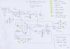
I need to create a latching output from the 'double-click' of a momentary push-button switch, but only within a fixed time period, say 2 seconds....

Here's the idea :

1/ A momentary switch is pressed once.

2/ After pressing the switch, a timer starts, with a duration of 2 seconds.

3/ If no further switch press is detected within 2 seconds, no further action is taken - the output of the latch remains OFF / low.

4/ If the switch IS pressed again before the 2 second time limit is reached, the output is latched ON / high.

5/ A further single switch press simply resets the latch output to OFF / low.

I've thought of using bistables, AND gates & counters, but am now really pulling my hair out....

Any ideas would be greatly appreciated.

Thanks all :)
 
Last edited:
hi,
Dont pull you hair out..:)

Look at monostables, either a mono ic or a 555 timer configured as mono.

1st push starts the 2sec mono, 2nd push gated with mono output.
 
Many thanks for the super-quick reply ;)

I think I should elaborate on what the circuit is for...

ATM, the momentary switch operates a CMOS flip-flop, which toggles a 48V motor on & off, by hard switching a power FET.

I need to be able to reverse the direction of the motor, but can only use the single "start-stop' switch on the machine.

A 2nd push of the switch usually stops the motor when it's running of course, so I'd have to overcome this problem as well.

My aim is to use a Power-FET H-bridge or dedicated driver IC to acheive the direction reversal - that's the easy bit !

I'm guessing this is really a sort of 'sequential logic' problem :confused:

hi,
Youve lost me a bit.:confused:
You say you want to start/stop with the same switch, but 'thats the easy bit', so I assume you can do that.

So are you saying you want to reverse the motor with the same switch..?

Hair pulling time.:)
 
Hello again

Yes, a single momentary switch must be used to start, stop & reverse the motor as needed.

I mentioned 'easy bit' in reference to the H-bridge motor driver IC I'll need to use to control the motor - these are usually quite simple to use & normally have a direction input pin 1/0.

The hard bit (for me) is getting my head around the logic required to perform 2 tasks with 1 SPST switch - each operation having 2 states...

Forward & Stop : single push start - single push stop

Reverse & Stop : 2 x pushes in <2 seconds - single push stop

I suppose a small microcontroler / PIC could be the realistic answer..
 
Last edited:
Hello again

Yes, a single momentary switch must be used to start, stop & reverse the motor as needed.

I mentioned 'easy bit' in reference to the H-bridge motor driver IC I'll need to use to control the motor - these are usually quite simple to use & normally have a direction input pin 1/0.

The hard bit (for me) is getting my head around the logic required to perform 2 tasks with 1 SPST switch - each operation having 2 states...

Forward & Stop : single push start - single push stop

Reverse & Stop : 2 x pushes in <2 seconds - single push stop

I suppose a small microcontroler / PIC could be the realistic answer..

hi,
A quick look indicates you could get the result using logic, but a PIC would be more elegant.:)

Do you have programming experience and the prommer.?
 
Hi

Very limited experience I'm afraid. I have a programmer / MPASM and other utilities, can compile asm & flash PIC's no problem. As for actual programming - nope.

Ironically, I came accross a 'clap switch' that used a 12F629 here : **broken link removed**

No code at all, just a diagram ! - a pity, because reading the circuit description, it looked pretty 'tweakable' as far as variables go etc....

Thanks

hi,
Looked at the link.
There are some excellent tutorials for asm programming of PIC's.
Look over Nigel's tutorials, link near my signature on this post.

Why dont you give programming a go, especially as you have got all the tools.:)
 
555 & 4013

Thanks for the PIC tutorial link and I really appreciate the comments :)

Sadly, learning from scratch is not going to happen - I work too many hours & TBH, could not justify the time (weeks/months) for a 1-off project.

Have spent this evening tinkering with a Mono 555 & D-type Flips - however not getting too far. The 2 sec 555 MS timing is OK, but have run into problems with the flip-flop logic. I'm going to end up with a mammoth circuit at this rate !

Really need to pay someone to write a snippet of code for me - something I can tailor & recompile to suit - would certainly be worth it

Hey-Ho :rolleyes:
 
Sorry if you've already got the "double-click" part down, but something I read in another thread is probably relevant to you since you're using a push-button: beware of bounce. When you press a mechanical button, it will bounce upon impacting contact, and usually cause the contact to be made and broken at least a couple of times. If you're going to use a PIC to interpret double-presses on this button, you need to be careful not to confuse the bounces for multiple presses.

Sorry if that's not relevant to your project, I didn't read some of the technical information since I can't contribute much to it, but I thought that might be useful to you.
 
The simplest way is to drive the flip flop into a 4017. The first output is gated to a change-over relay. The second output keeps the relay on and is gated to a FET.
The third output keeps the relay on but turns off the FET. The fourth output turns off the relay. The fifth output turns on the FET. The sixth output turns off the FET. The 4017 then cycles again.
You will need 5 gating diodes. With this circuit the relay will be closed before power is applied. You also have a delay before changing the relay.
 
Last edited:
Switch Bounce

Hi - thanks for your post :)

Any bounce is eliminated with a parallel 0.1uf cap + 10K resistor across the switch.

Still struggling with the CMOS / 555 / RC circuit - really need someone who knows about programming a small micro : 12F509 / 629 etc :confused:
 
The simplest way is to drive the flip flop into a 4017. The first output is gated to a change-over relay. The second output keeps the relay on and is gated to a FET.
The third output keeps the relay on but turns off the FET. The fourth output turns off the relay. The fifth output turns on the FET. The sixth output turns off the FET. The 4017 then cycles again.
You will need 5 gating diodes. With this circuit the relay will be closed before power is applied. You also have a delay before changing the relay.

:eek: WOW - that sounds like fun !

I know it must have taken you an absolute age to type all that & thank you ;), but could you possibly eloborate on
what each stage of the decade counter controls / toggles - ie what the FET is doing & what the relay is toggling ?

Perhaps a 1-6 list of events / operations ?

Many thanks :)
 
I have fully explained what each output of the 4017 does and how it is connected.
The relay performs the reversing and the FET turns on after the relay is engaged. Draw the circuit from my description.
 
Last edited:
Variation on colin55's idea to use a 4017 as a sequencer attached. Haven't tried it, but I think it looks OK.
You could probably rationalise the gates a bit -I just prefer to use the Schmitt trigger inputs on the 4093s -keeps the monostable outputs nice and clean.
Not as elegant as the PIC option, I'm sure -but nice and simple for a 'one off' project! :)
 

Attachments

  • switchdet.jpg
    switchdet.jpg
    414.6 KB · Views: 526
My circuit just needs one 4017, five diodes and a change-over relay. You have all the other components.
 
Circuit variation

Thanks a milliion for taking the time out to draw this schematic - I'll certainly get it breadboarded up tonight & will let you know how it goes..

I count 11 x Nand Schmitt's (3 x 4093's), Johnson Counter plus Comparator - quite a lot of veroboard work to be done, but I'm game for anything ATM :D !

In the meantime, I'm going to pop a post in the PIC section re the possibility of someone being able to help draft a few lines of code for a 12C509 etc.

Have download the trial version of the PicBASIC compiler & PICaxe suites - but head really spinning now...

Thanks very much once again ;)
 
My circuit just needs one 4017, five diodes and a change-over relay. You have all the other components.


I did try and draw out your circuit from your description, but I had to admit defeat --not very bright I'm afraid!:)

I'd like to see your simpler version, if you have a couple of minutes to scribble it down......
 
My circuit just needs one 4017, five diodes and a change-over relay. You have all the other components.

:) thanks for your suggestion - really appreciated, but I'd like to keep away for using mechanical switching - especially for the reversal. As an added bonus, if I can use one of ROHM or ST's range of excellent high power, reversible H-Bridge drivers, I can have PWM speed variation as well - a double whammy :eek:
 
Last edited:
Status
Not open for further replies.

Latest threads

New Articles From Microcontroller Tips

Back
Top