Continue to Site

Welcome to our site!

Electro Tech is an online community (with over 170,000 members) who enjoy talking about and building electronic circuits, projects and gadgets. To participate you need to register. Registration is free. Click here to register now.

  • Welcome to our site! Electro Tech is an online community (with over 170,000 members) who enjoy talking about and building electronic circuits, projects and gadgets. To participate you need to register. Registration is free. Click here to register now.

Thin film LED circuit design

Status
Not open for further replies.

gnomeh1200

New Member
Hello, first post on this forum. Retired from the machine control end of the electrical industry. I thought I could survive in the SS electronics world and have done so for many years. I now have a problem I would like to resolve “with a little help from my friends”. I have a large number of LED exterior night guard lights which are part of my area security system. To put it mildly, after a number of different fixture failures, enough is enough. They all seem to use LED counts from 50 to 70 LEDs (50W rated), mounted via thin film to a aluminum backer plate. They fail after very little usage. Why replace the entire fixture just to fix a $5.00 problem!!! 120VAC input. My assumption is series/parallel with a cap and resistor in line to drop voltage and smooth out the current. Can’t find any suppliers for replacement similar boards. Thought I might build some to use as replacements - got nothing better to do. Any ideas?????? See attached pic of removed board. THX, Doug
 

Attachments

  • image.jpg
    image.jpg
    1.6 MB · Views: 197
That is 70 LED assemblies. A single white LED is about 3 V, but it's difficult to say if they would all be in series. Also, each little LED assembly could be more than one LED. It's fairly common for assemblies like that to have two LEDs in series.

It's very difficult to unsolder LEDs like that from the aluminium PCB, but it's not too difficult to short out faulty LEDs.

I would firstly measure the voltage of one LED. If you take a 12 V supply, and put a 1 k resistor in series, you can power a single LED assembly from that, and measure the voltage across the LED. I would expect around 3 V or around 6 V.

I would then trace out the circuit of the circuit by using a circuit tester to find which LEDs are connected directly to the -ve supply, then which LEDs are connected to the other side of those LEDs, and so on.

You haven't shown the driver circuit. There is a wide variety of circuits used to drive LED circuits.

I suggest linking out the faulty LEDs if possible, and reducing the power used to drive the LEDs. If you cut down the power, the LEDs will run cooler and will probably last far longer.

Some circuits will automatically generate less power if there is a smaller LED voltage caused by shorting, but some will be increase the power. It's often quite easy to cut down the power with a minor circuit modification. It might be worth cutting down the power on a new light.
 
THX for your response. You confirm, more or less, what I expected as a reply. It does, however, raise more questions in my mind. The supply voltage for this LED panel is 120VAC. You mention a driver circuit for the LEDs. Do these LEDs only function on low voltage DC? Based on what I see on the circuit board there is no provision for voltage conversion. I may be wrong??? 120VAC is applied as shown in pic. Also, I researched the additional circuit included below. Basically, I’m confused with what see on the circuit board I removed from the light Assy. THX for your attention. Doug
 

Attachments

  • 77E62E27-364C-4629-8577-51F8D2ABD36B.jpeg
    77E62E27-364C-4629-8577-51F8D2ABD36B.jpeg
    2 MB · Views: 202
With reference to your schematic, think what happens on each of the AC cycles. When the top pin is positive then the outer LEDs will light, when negative the inner will light. Are you sure there's only 12 in each series string?

Mike.
 
An individual LED will only light with a low voltage and the current in one direction. For white LEDs the voltage is about 3 V, but it's the current that should be controlled, not the voltage. LEDs should not be connected to a large reverse voltage or they will be damaged. If they are connected to a forward voltage that is mor than their normal voltage, a large current will flow and they will burn out.

The circuit you show has a capacitor in series. Each time the mains goes positive, it will charge up on way, and it will charge the other way when the mains goes negative. Because the mains is a smooth waveform, the voltage only rises or falls relatively slowly, taking 8.33 ms to go from fully positive to fully negative or vice versa, and there are no sudden changes, so the current to charge or discharge the capacitor is small. The size of the capacitor and the frequency and voltage of the mains are what limit the current.

It's a bit like a tidal estuary filling up and emptying each tide. The flow of water in and out of the mouth of the estuary depends on how high the tides are, and how often, and the area of the estuary.

The design is based on a certain mains voltage and frequency, so 120 V and 60 Hz in the USA, which won't change much, so the size of the capacitor can be chosen to give the required LED current. The LEDs are supplied from the mains without there being any actual voltage conversion. The overall LED voltage, probably around 36 V in the case of your circuit, it too small to effect the current much.

The 1 kOhm resistor is to limit the current at turn on, when the voltage can change quickly. Without the resistor the current would be very large for a few microseconds, which could do a lot of damage.

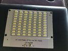
I don't think that the LEDs in your first picture used that circuit exactly, because the panel is marked with a "+" and a "-" sign. It could be that it is a similar circuit, with a bridge rectifier, in which case the current will still be controlled by a capacitor. However it could also be a completely different design of circuit.
 
THX for your comments, Mike. The most recent pic is just a stock pic of an LED circuit using a 120VAC source. Think in terms of my first posted pic. There are 7X10 rows in the original PCB for the light fixture. If I understand your scenario, you would need even parallel strings wired in series??? Perhaps the best solution would be suck it up, go out and buy new fixtures as required and just thank GOD for China seriously, there is room for a driver in the housing if required. Maybe more important would be can I source the LED array 70 LEDs in an area of “2”x2.75” to fit the reflector housing
Doug
 
Diver300, Thx for your comments. Based on your comments and others I now feel that It is a great intellectual exercise but ultimately unrewarding. Especially given the fact that I can replace the entire fixture for about 18 bucks. Although there are no signs of overheating I suspect it is a “wonky” circuit. They only operate during an alarm event or the one time per month test cycle. What happened to high lumen output, long life claims. Yes they are China specials THX
 
Status
Not open for further replies.

Latest threads

New Articles From Microcontroller Tips

Back
Top