Continue to Site

Welcome to our site!

Electro Tech is an online community (with over 170,000 members) who enjoy talking about and building electronic circuits, projects and gadgets. To participate you need to register. Registration is free. Click here to register now.

  • Welcome to our site! Electro Tech is an online community (with over 170,000 members) who enjoy talking about and building electronic circuits, projects and gadgets. To participate you need to register. Registration is free. Click here to register now.

thermistor based airflow sensor - opamp help

Status
Not open for further replies.

steaky

New Member
Hi,

I am trying to design a thermistor based airflow sensor, but I am having trouble with getting the output voltage at a suitable level.

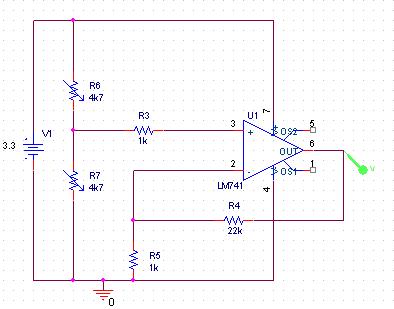
My current circuit takes two 4k7 positive coefficient linear thermistors set up as a potential divider and the second thermistor is externally heated with an additional resistor so that the potential divider is constantly biased one way.

However, the output has a very small swing of 0.1V - when measured through my 10bit ADC is only 30points. Given that the line could be noisy this isnt acceptable.

I tried amplifying the signal through a non-inverting op-amp but I need to reduce my input voltage by around 1.6V before I can amplify it - any thoughts?
 
Need a schematic of your setup.
 
the concept you're using is similar to the differential heating anemometer concept in this article:
http://electronicdesign.com/Roadblo...ifferential-heat&catpath=test-and-measurement

The circuit:
**broken link removed**

However, thermal sensors are quite lousy in detecting airflow (in my opinion), since it detects ambient temperature. When wind blows on a thermal sensor, the temperature goes down, which looks promising, but this also means the ambient temperature has reduced.

This is why my LM35 doesn't shoot back into the nominal room temperature when I shut the fan off. It goes back down only after.... like eons. I remedied this condition using some ideas from the article provided.

That circuit's lousy, by the way, I've tried it, and another guy from the 'net also attested to it. Just an idea.
 
60-circuit.jpg


The thermistors have a linear response, and only one is subjected to cooling via airflow.
 
Hi,
However, the output has a very small swing of 0.1V - when measured through my 10bit ADC is only 30points. Given that the line could be noisy this isnt acceptable.
I tried amplifying the signal through a non-inverting op-amp but I need to reduce my input voltage by around 1.6V before I can amplify it - any thoughts?

If audioguru's here, he'd bash at you using a 741. It's an extremely lousy IC.:D
What is it that you're trying to amplify? The 0.1V output? A single stage differential amplifier is enough to obtain the desired output. See the datasheet of LM358, they're better op-amps, not the best though.
 
I know 741's are shoddy, but it was more about getting the theory right first.

The because of the thermistors dynamic range, but I am only going to have them running at about 15deg difference and so the resistances will be approx 4k7 and about 5k.

Using potential divider equation I want to keep a value of around 1.7V (and when no diff its 1.65V).

Ideally I want to constantly drop about 1.6V before amplifying the actaul difference... (or just amplify the difference between the two readings)

thanks in advanced
 
Audioguru!!! Where are you?!!
steaky, I'm no expert but I have built my own anemometer, and trust me, airflow sensors using thermal properties is very tricky. Primarily, what is the maximum change in the thermistor from still air to a full fan blast? That is VERY important. Even a designated temperature sensor LM35 doesn't detect airflow properly, I've tested it feverishly.
 
Thermistors are very slow to measure airflow.

Here is a solution published by Steve Woodward, university of North Carolina. It uses transistors as sensing elements. It's output is linearized and digitized.

Boncuk
 

Attachments

  • AIRFLOW.PDF
    157.3 KB · Views: 2,619
Audioguru!!! Where are you?!!
steaky, I'm no expert but I have built my own anemometer, and trust me, airflow sensors using thermal properties is very tricky. Primarily, what is the maximum change in the thermistor from still air to a full fan blast? That is VERY important. Even a designated temperature sensor LM35 doesn't detect airflow properly, I've tested it feverishly.

Hi Vizier87,

you might also want to take a look at the circuit designed by Steve Woodward. It heats one transistor for a constant temperature difference of both to be 50deg/C. So the airspeed doesn't really matter. Measuring airflow with a single LM35 doesn't take ambient temperature into account, and therefor can't be precise.

I wish I had an anemometer of his design when crawling through air channels and pipes measuring airspeed. The hot wire anemometers just need a little kick to become unusable, and replacement and calibration was awefully expensive.

Two transistors, mounted side by side don't take much more space than the hot wire pen, but they certainly can stand a lot more mechanical stress.

I also designed a single sided PCB layout for the anemometer. There are four wire jumps - necessary only for a 100% ground fill. The sensor board is the small one on the right side.

Boncuk
 

Attachments

  • ANEMOMETER-I.gif
    ANEMOMETER-I.gif
    39.4 KB · Views: 1,226
Last edited:
I did build it myself (from the article I provided as the reply, the design which is from Steven Woodward in ElectronicDesign.com **broken link removed**), and I have to say I'm not very impressed with the outcome.

How about yours, Hans?
 
Measuring airflow with a single LM35 doesn't take ambient temperature into account, and therefor can't be precise.

Yes, it isn't. I remedied the problem using additional networks, and the sensitivity is far better than the 'tranemometer'. It's just it happens to be my thesis about solid state weather systems and I don't want to spill too much details until it's completed, then I'll post a complete documentation.
 
Hi, and thanks for everyones input.

It really helped just have specific terms for everything, but I think I am going to run two LM35 (or other linear temp->voltage sensor) through an instrumental differential amplifier.

This simulates perfectly, and should be relativly cheap to build.
Thanks again for the help.
 
Well, the nice part about a thermistor is that, if you crank up the current, they're self-heating. You don't want that on the ambient temp sensor but DO want it on the airflow sensor. This improves the accuracy.

And more heating=greater temp rise=larger signal.

Car Mass Airflow Sensors are all self-heated thermistors. An interesting feature is that it detects MASS, not just SPEED. At higher altitudes, the lower pressure not only brings less air mass into the cylinder but less cooling value to the thermistor. This all works out- the cooling value on the MAF sensor is totally proportional to the mass of air entering the cylinders, which is what's needed to calculate fuel mixture.
 
Hi, and thanks for everyones input.

It really helped just have specific terms for everything, but I think I am going to run two LM35 (or other linear temp->voltage sensor) through an instrumental differential amplifier.

This simulates perfectly, and should be relativly cheap to build.
Thanks again for the help.

That's unwise. Like we said, LM35 isn't a good airflow detector. I'd like to tell you the rest on how to use it properly, but like I said, my design is still being tested. It'll be better if you construct the circuit Boncuk gave and tell us how it comes about. IF it's not good I'll be gloating around for a few posts. Hehehe!! Just joking Hans.
 
wow. how does it work?
With what I just said. The denser the air, the greater the cooling. Thus the thermistor reading doesn't know if it's fast, low pressure air or slower, denser air. Its reading is for mass airflow, not airflow. This saves you from having to combine an air pressure sensor, air temperature sensor, and airflow rate sensor.
 
I did build it myself (from the article I provided as the reply, the design which is from Steven Woodward in ElectronicDesign.com **broken link removed**), and I have to say I'm not very impressed with the outcome.

How about yours, Hans?

Hi Vizier87,

at the moment I have no reason to push building the circuit. (I designed the PCB layout just to keep me busy.) The only airspeed - hence volume flow - I have to measure is produced by two large fans for building air treatment. For this application a differential pressure transducer is used. It measures the (negative) plenum pressure against the (more negative) fan intake pressure. The result (difference) is dynamic air pressure which then is converted to airspeed (m/s) and via fan cross section and time calculated in m³/hr.

The only provision is a cone (nozzle?) shaped air inlet at the fan for smooth air flow along the fan case.

The fan intake pressure is measured by a closed loop of copper pipe (6/4mm dia) connected to four openings through the fan case - flush with it - about 2cm in front of the blade edges.

Since both sides of the differential pressure sensor "see" the same air temperature compensation is not necessary.

The entire arrangement is similar to the function of a pitot boom, just muuuuch cheaper.

Regards

Hans
 
That's unwise. Like we said, LM35 isn't a good airflow detector. I'd like to tell you the rest on how to use it properly, but like I said, my design is still being tested. It'll be better if you construct the circuit Boncuk gave and tell us how it comes about. IF it's not good I'll be gloating around for a few posts. Hehehe!! Just joking Hans.


I have used a device similar to the LM35 before and the response is fairly quick. I was planning on heating one of the LM35's hotter using a transistor driven resistor (using a PIC as a control - measuring the mark-space ratio)
I simulated the circuit in pspice (using voltage source in place of the LM35) and with a 0.1V diff (10deg) I was outputing 0.95V (this gives me around 31points of ADC per degree of difference).
Realistically the environment wont go less than 5deg or greater than 50deg so I should be ok.

Hello, How is it possible to heat LM35? Could you explain me in details? Maybe The Circuits schematics will be very helpful. I am looking forward to hearing from you.
 
Status
Not open for further replies.

Latest threads

New Articles From Microcontroller Tips

Back
Top