Continue to Site

Welcome to our site!

Electro Tech is an online community (with over 170,000 members) who enjoy talking about and building electronic circuits, projects and gadgets. To participate you need to register. Registration is free. Click here to register now.

  • Welcome to our site! Electro Tech is an online community (with over 170,000 members) who enjoy talking about and building electronic circuits, projects and gadgets. To participate you need to register. Registration is free. Click here to register now.

Theory and confusion of cross-over among individual filters

Status
Not open for further replies.

PhillDubya

New Member
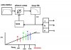
If I have a filtering system, with 3 frequencies, and three filter for each frequency, can I ever have cross-over?

To me it seems as though you wouldn't be able to, because each signal has its own filter.....


I.E.

f1=100Hz, f2=200Hz, f3=250Hz

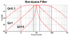
Even if you find out, that there is some cross-over among the frequencies at the -3dB point (.707 x Ampitude), they are each going to there own filter. So, it shouldn't matter even if they mathematically have cross-over when graphed, correct?
 
Last edited:
Are these band pass, high pass, or low pass filters?

Are they in series or parallel.

What do you mean by cross-over?
 
Are these band pass, high pass, or low pass filters?

Are they in series or parallel.

What do you mean by cross-over?

Band Pass Filters

"Are they in series or parallel."
I was assuming parallel. That is a good question, and may be the deciding factor. I honestly don't know though if you would typically run them in parallel. The idea is that I am transmitting and receiving these signals that I gave above, they theoretically will have cross over.

"What do you mean by cross-over?"
See the A vs f graph, the low pass has cross over with the high pass.
Cross Over This is an LP and HP, but it still the same idea of signal cross over.


I am trying to figure out, if due to cross over, one signal that is meant to only be passed for one filter will actually get passed through another, by being so close to the other frequency, when its at the -3dB point?

Thanks for responding.
 
Last edited:
The circuit is called "an active crossover circuit for a two-way speaker".
It is made with a high-pass filter for the tweeter and a lowpass filter for the woofer. The filters are in parallel. The low frequencies are subtracted from all the frequencies to make the high-pass filter.

You can see on the curves that a lot of the low frequencies go to the tweeter but as the frequency becomes lower then less amplitude is passed.
Also the curves show that a lot of the high frequencies go to the woofer but as the frequency becomes higher then less amplitude is passed.

These filters are fairly simple "second-order" type with a fairly gradual slope. Third-order and fourth-order filters have a sharper slope.

Your frequencies are too close together to use this simple filter. You need high-Q bandpass filters.
 
audioguru: Your response is greatly appreciated, however, that link to the cross-over circuit, is only an example of the idea of cross-over, to explain what I was talking about to crutschow.

Maybe I should rephrase my question for clarity.

I am transmitting 3 frequencies: f1=100, f2=200, f3=225

Each frequency detected at the receiver does something for me, some function.

So, at my receiver, I want to have three BANDPASS filters to detect when I am receiving each signal. The center frequency of each filter is: f1=100, f2=200, f3=225.

And lets assume that the pole cut off and slope characteristics of my filters conform to roughly my center frequency plus or minus 17%.

Therefore, for my first filter:
fc=100Hz, fb=83Hz, and fa=117Hz

Second filter:
fc=200, fb=166, fa=234

Third:
fc=225, fb=186, and fa=264.

My fb and fa, are my 3db points, or where the Amplitude = .707.

So, as you can see, the bold numbers above have cross-over. Basically, they are too close together, and the second filters BW is so wide, or maybe close to the third filter's, that it will end up passing some of my third filters signal. Same with the third filter: it is either to close to f of the 2nd, or its BW is too wide, and it will end up passing some of the 2nd's signal?


Is my underlined statement correct, is basically what I am asking?

Thanks:)
 
Last edited:
To distinguish between 3 frequencies you'd have to compare the output from all 3 filters and choose the one with the highest amplitude. Even then, you wouldn't know for sure if the signal was exactly in the passband of one filter without also monitoring the amplitude of the unfiltered signal. Not to mention what would happen with a non-sinusoidal input.
Typically a PLL is used, instead of BPFs, for tone signaling decoding.

Exactly. With my set-up, lets say at any given time I could be transmitting any of the frequencies. Hypothetically, upon receiving, lets say f1=open, f2=close, f3=off, these are my functions. The cross over that I highlighted in bold, could cause either a close OR an off function to happen, because of my cross-over problems, correct?

Especially, if at the receiving end, on each filter output, I have some sort of logic, to distinguish whether or not the amplitude of my signal is at a set point.

For example: I I am monitoring not only the frequency and whether it has passed but whether it meets a minimum amplitude. As long as the amplitude is above the set-point, it will activate, but I won't know which, and most importantly, neither will my system.
 
Last edited:
Your bandpass filter have a low Q of about 2.9. The Q is the ratio of the center frequency to the -3db bandwidth.

Look at the curves of a single bandpass filter and you will see that a 200Hz filter with a Q of 2.9 will pass 100Hz at about -12dB which is about 1/4th its original level. It will also pass 250Hz at about 1/4th its original level.

Make the Q higher for a narrower bandpass or connect two filters in series for a narrowed bandpass.
 

Attachments

  • bandpass filter response.PNG
    bandpass filter response.PNG
    8.2 KB · Views: 185
audioguru: Your response is greatly appreciated, however, that link to the cross-over circuit, is only an example of the idea of cross-over, to explain what I was talking about to crutschow.

Maybe I should rephrase my question for clarity.

I am transmitting 3 frequencies: f1=100, f2=200, f3=225

Each frequency detected at the receiver does something for me, some function.

So, at my receiver, I want to have three BANDPASS filters to detect when I am receiving each signal. The center frequency of each filter is: f1=100, f2=200, f3=225.

And lets assume that the pole cut off and slope characteristics of my filters conform to roughly my center frequency plus or minus 17%.

Therefore, for my first filter:
fc=100Hz, fb=83Hz, and fa=117Hz

Second filter:
fc=200, fb=166, fa=234

Third:
fc=225, fb=186, and fa=264.

My fb and fa, are my 3db points, or where the Amplitude = .707.

So, as you can see, the bold numbers above have cross-over. Basically, they are too close together, and the second filters BW is so wide, or maybe close to the third filter's, that it will end up passing some of my third filters signal. Same with the third filter: it is either to close to f of the 2nd, or its BW is too wide, and it will end up passing some of the 2nd's signal?


Is my underlined statement correct, is basically what I am asking?

Thanks:)

If you want to be able to treat the outputs of the three filters as three independent signalling channels then you will need to make sure that they have adequate attenuation at the other frequencies. Looking at the numbers, the tightest spec will probably me making the 250Hz filter reject the 200Hz component. You need to make the response to the highest level 200Hz component be low enough so as not to interfere with your 250Hz level measurement.

You could do this with active filters, although they will be narrow band and will probably require tuning. No major dramas though.

You could make a simple tuned receiver for each tone - then you would use baseband filtering to reject the other tones.

If you are good at DSP you could do a single chip solution...

Guess you can't use a standard DTMF tones? There are single chip solutions then.
 
another way would be to use a single PLL circuit and window comparators fed by the VCO control voltage. all he would have to do is set the 1st comparator to trigger when the CV is locking the VCO to a 100hz signal, the second for 200hz and the 3rd for 250hz. if the pll's free-run frequency was outside of the activation band (400hz for instance) then the comparators would all be off when the VCO is idling. for a low frequency pll, the lock ranges would be narrow enough that false triggering could be eliminated with a simple time delay and a NAND gate. if the comparator is active for too short of a time, the trigger outputs remain inactive. that way, random trigger events from noise, or the VCO CV passing through the windows of the other comparators (such as the CV dropping from the idling range through the 250 and 200 ranges as the PLL accquires a lock on the 100hz signal) will not false trigger any of the outputs.
 
something like this...... the "a" output is only high while the CV is within the range between the red lines, the "b" output is only high while the CV is within the range between the green lines, and the "c" output is only high while the CV is between the blue lines.
 

Attachments

  • pll-window-comparator.jpg
    pll-window-comparator.jpg
    26.2 KB · Views: 228
Status
Not open for further replies.

Latest threads

New Articles From Microcontroller Tips

Back
Top