Continue to Site

Welcome to our site!

Electro Tech is an online community (with over 170,000 members) who enjoy talking about and building electronic circuits, projects and gadgets. To participate you need to register. Registration is free. Click here to register now.

  • Welcome to our site! Electro Tech is an online community (with over 170,000 members) who enjoy talking about and building electronic circuits, projects and gadgets. To participate you need to register. Registration is free. Click here to register now.

Tenma 72-720 Oscilloscope - Where is the "TP terminal"

Status
Not open for further replies.

Rocktronic

New Member
I bought a used Tenma 72-720 for cheap off eBay. I got a trace and could dial it in but it was a little fuzzy and some slight curvature at the edges on a flat line. I don't know if the electrolytics leaked out goo or if it was glue but I decided to replace all the electrolytics to be safe.
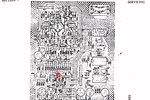
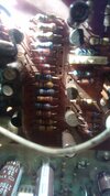
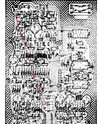
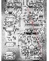
Now I'm trying to perform the calibrations listed in the manual and there are instructions to short or open the TP terminal on the V PCB.
I can't find a "TP terminal" on the Vertical Amplifier board.

Does anybody know where that terminal is?

Thanks
 
Ok, I think "TP" means "Test Points". I can't find anything labeled but there are two buttons of solder on the bottom of the V PCB between the 8 pin (7 used) connector from the PS and the edge of the PCB with no component or jumper.

Can anyone confirm?

These were also sold as Hung Chang OS-620 and many other brands.
 
I think I found it thanks to Kieth Walker on another forum.
 

Attachments

  • Tp.jpg
    Tp.jpg
    308.7 KB · Views: 176
I found it on the board. TP next to a rectangle with three holes (ports) and line dashes pointing to one of the holes and a pin on an adjacent connector.
I guess that means to jumper the center hole and the first (nearest) pin on that connector?
 

Attachments

  • TP.jpg
    TP.jpg
    471.4 KB · Views: 175
That dashed line actually extends past the connector over to a white wire soldered to the board and the other way to either to a capacitor or maybe all the way over to the other end of that wire which is also connected to the board,

I wonder if that wire is already shorting the TP or is it just the two holes in the rectangle that are closest together?
 
I found the dashed line on the layout as well, it does extend between the two ends of a white wire.

So, is that wire the jumper between the test points, or just indicating a jumper?
Which terminals should I short?

Thanks
 

Attachments

  • V-PCB.jpg
    V-PCB.jpg
    1.1 MB · Views: 176
When I look closer at the layout, it only shows the two outer holes within the box while there is a third hole within the box on the actual board. Now I think it's either those two outer holes within the box or the white wire connected at each end of the dashed line.

Does the "TP" signify the box or the dashed line?
 

Attachments

  • V-PCB2.jpg
    V-PCB2.jpg
    1 MB · Views: 168
  • TP.jpg
    TP.jpg
    471.4 KB · Views: 170
Status
Not open for further replies.

New Articles From Microcontroller Tips

Back
Top