Continue to Site

Welcome to our site!

Electro Tech is an online community (with over 170,000 members) who enjoy talking about and building electronic circuits, projects and gadgets. To participate you need to register. Registration is free. Click here to register now.

  • Welcome to our site! Electro Tech is an online community (with over 170,000 members) who enjoy talking about and building electronic circuits, projects and gadgets. To participate you need to register. Registration is free. Click here to register now.

Temperature sensor with a display (help)

Status
Not open for further replies.

Giggabite

New Member
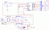
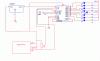
Hi guys im trying to build a temperature sensor which has a reading reflecting on a digital display. Similarly to this one but the problem im having is that i need to simulate this on a bradboard with a bench supply voltage . Can anyone assist in giing alternative schamatics to adjust the circuit such that it can be completed in a lab . I have a project to complete and its doing my heading . Thank you all !


**broken link removed**
 
hi,
I have made a few changes, see image.

You have not said exactly what help you need.:)

Can anyone assist in giing alternative schamatics to adjust the circuit such that it can be completed in a lab

Do you mean a software/program simulation.?
 

Attachments

  • 9.gif
    9.gif
    12.8 KB · Views: 248
Last edited:
Thanks for the quick response . Im not sure if im able to simulate the whole circuit to a bread oard. As we can all see , the bottom part of the circuit functions with a high voltage supply which is diluted by a step down transformer . Now my question is . Is this whole circuit feasible and how do i simulate it to a breadboard in a lab, with probably a signal generator as supply voltage ? I assumed there could be an alternative circuit without the bottom half of the circuit comprising of a high voltage supply, step-down,transformer, regulator etc? I dont have a problem with the top part of the circuit has it has a reasonable voltage supply ! So how do i substitute the bottom higher voltage panel ?

thanks
You would use a bench 'dc' power supply set for +5V [ this would replace the 7805]

Use a variable resistor, say about 5KΩ connect one end to +5V and the other end to 0V,,, the wiper would be the Vref to the ADC, [ this would replace the LM317]. The Vref would be good enough for a bench test.

Do you follow OK.?:)

EDIT:
Look at this image.
 

Attachments

  • 9.gif
    9.gif
    9.6 KB · Views: 242
Last edited:
You would use a bench 'dc' power supply set for +5V [ this would replace the 7805]

Use a variable resistor, say about 5KΩ connect one end to +5V and the other end to 0V,,, the wiper would be the Vref to the ADC, [ this would replace the LM317]. The Vref would be good enough for a bench test.

Do you follow OK.?:)


I follow slightly , are you able to provide a schematic ?

Thanks .
 
Last edited:
Just a heads up, you do realize the LEDs will display binary not at all like a thermometer type bargraph.

I assumed i could connect the led's to a binery count driver , 555 timer and then a display ...something of that configuration is what i may want to add up to garnish the circuit . Is there an extra schematic to add to the one above.

thanks !
 
Are you saying you want a numeric digiital display!!:rolleyes:

Absolutely.......my tutor is pressuring us to go an extra mile and to be honest , the above configuration has helped a lot . But now the numeric display will crucify the task with surgical precision . I have also written this req on this forum plus your response in my LOGBOOK. EVERY HELP I GET THROUGH RESEARCH HAS TO BE RECORDED .

thanks !

Sorry, but can you explain with a little more detail.:)
 
Sorry, but can you explain with a little more detail.:)

I thought if the temperature reading could be read on a numerical digital display . From the circuit above i thought we could use this principle

The output of the ADC can be interfaced to a 7-segment diaply using a 7-segment driver or the digital output can be interfaced to a PC / microcontroller. The bottom portion of the schematic shows a fixed and a variable power supply which inputs 220 volts AC from the wall outlet in your house, the transformer then steps-down it to 18 volts AC (9-0-9 centre-tapped), which is then converted to DC using bridge rectifier.

here is the link

Temperature Sensor with Digital Output
 
A microcontroller (cough) like the 16F88 (muxed displays) or 16F886 (non muxed) could do the A/D & display decoding & driving all within a single part.
 
Status
Not open for further replies.

Latest threads

Back
Top