Electro Tech is an online community (with over 170,000 members) who enjoy talking about and building electronic circuits, projects and gadgets. To participate you need to register. Registration is free. Click here to register now.
Welcome to our site! Electro Tech is an online community (with over 170,000 members) who enjoy talking about and building electronic circuits, projects and gadgets. To participate you need to register. Registration is free. Click here to register now.
Another thought: If you bring the brake signal to the rear, the circuit I proposed can be easily modified for that. The main advantage of this would be the elimination of the one turn-signal pulse delay before the sequence starts.
I simulated the same circuit on proteus and it worked fine.
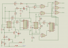
An extra bonus is that if you wire the pin 4 (reset) of 2nd 555 (U13) to Q2 or Q3 of 4017 (U3), the signal lights would flash simultaneously first for a while before switching to the A.B,C sequence. The 2 buttons on the left are for turn signal and brake switches.
See the schematic attached. All the pin numbers are there for reference or breadboarding.
Just noticed a couple minor errors in my schematic. C3 should go to the other side of R4 to provide filtering for V+. Also the input debounce circuit consisting of C4 and R5 was delaying the brake light signal by about 80ms which is significant from a reaction time standpoint of the following vehicles, so I added a diode to make the delay negligible.
The diode should be rated 1A or more so the initial current surge to charge C4 doesn't zap the diode.
Let me get this right. If there is a high to the input, the pulse detector goes high. This starts the first counter. The inputs to U11 are both high so that turns on all lights at once. If there are no additional pulses but the input stays high (brakes on) the sequence start counter U3 doesn’t get to the second output Q1 and the sequencer clock never starts. If there is another pulse, the high out from Q1 is fed back to the input and stops the counter from incrementing. U11 output goes low so all the lights don’t go on at the same time. The sequencer clock and U5 make the lights blink in sequence.
Looks like it may work. Circuit has to be duplicated for the other side, right? I thought this was kind of complicated but now I realize you put a lot of thought into it and it should work.
The delay for the turn signals is not really a problem. First all lights are on one side then it starts sequencing. That’s OK. Main thing is no delay when brakes are put on. I found a definite difference between the response time of LEDs and regular filament bulbs, apparent when using an electronic flasher driving both in parallel.
Thanks for the idea, now to find parts to try it out.
Your description of the basic circuit sequence is correct. To clarify, you are referring to U3-Q1 output (U3-01 on my schematic), not transistor Q1.
Yes, you need two circuits. You can share V+ and two of the CD4081 AND gates (of the four gates in one chip) between circuits. Everything else needs to be duplicated. To reduce chip count, you could use a 556 (dual 555) if you like.
Edit: I know the circuit is reasonably complicated, but I don't think it can be done much simpler unless you go to a microprocessor (which is why people use microprocessors).
I have ordered the parts from Mouser and have part of the circuit working. What would you recommend for circuit board layout software. I am familiar with stripboard and point to point wiring but this looks like something that would lend itself to a pcb. I am running Windows 7 and Windows XP, not Vista or Mac.
With the original car wiring the brake indication overrides the turn indication. That is an important safety feature which will be lost if you let the turn indication dominate instead. I don't know about the US legislation, but over here in the UK that sort of mod would not be legal and would invalidate the vehicle insurance.
The easiest would be to use PCB fab companies that provide dedicated layout software which generates a layout that goes directly to their fab facility. Examples are ExpressPCB and PCB123.
Eagle is also a commonly used layout software the works with any PCB fab house but it generally has a much steeper learning curve.
In regards to the brake override function. When the brakes are applied concurrently with the turn signals on a vehicle with combined turn and brake lamp filaments:
On the side that one is NOT turning towards the brake light is on steady
On the side towards which one is indicating a turn the brake lights are flashing.
If the brake overrode the turn signals then there would be no way to indicate that the car was about to turn. Somebody following may try to go around the “slow driver” not realizing that the reason for the reduction in speed was that the driver was intending to turn. This could be a problem.
I think it is imperative that the turn signal always work, brakes on or not. Since all cars now have center mounted brake lights there are at least two different places where it shows intention to slow down. Maybe we need to add a center brake light to the Comet. However with three 2357 bulbs instead of the original 1157 single bulb I think it will be pretty bright.
Now, some cars have the brake and turn signals on separate lamps. In that case, the circuit would be much simpler. This may be the way it is in the UK, I dunno.
Somebody following may try to go around the “slow driver” not realizing that the reason for the reduction in speed was that the driver was intending to turn. This could be a problem.
But less of a problem, I think, than being shunted up the rear by some idiot who was distracted by the flashing light but hadn't noticed the reduction in speed
Now, some cars have the brake and turn signals on separate lamps. In that case, the circuit would be much simpler. This may be the way it is in the UK, I dunno.
As I recall, vehicles in the U.S. that shared one light for brakes and turn signals, kept the turn signals operating when the brake was simultaneously applied. The appearance of a steady light on the side opposite of the blinking light was readily interpreted by the following vehicles as the brakes being applied.
The brake light filament is ten times brighter than the regular tail light. The original car had one lamp on each side. The Comet will have three on each side. When all three on one side light up it will be very apparent you are slowing down. This is an old car and doesn't stop on a dime, though we did install disc brakes on the front. I added some air conditioner duct aluminum tape to the "bucket" behind the plastic lens for better reflectivity. It makes a big difference.
BTW, I have downloaded the BitTrace and am going through the tutorial. Looks promising , especially if it can do autorouting for pcbs.
Last time I checked there were two filaments in a running/brake, turn, hazzard lamp. One, lower lumens, is for the running lights. The other, higher lumens, is for brake, turn-signal. and hazzard. U.S. Standard.
When you step on the brake, and the turn signal is energized, the turn or hazzard signal overrides the brake signal. you will need two such circuits to drive the tail lights.
The brake light filament is ten times brighter than the regular tail light.
I will be using a CF13JL02 universal turn signal flasher. It flashes at about 80 times a minute independent of the load applied. They are popular with the motorcycle LED conversion crowd. So the missing pulse detector set at one second would be about right.
BTW, some of the motorcycle LED conversion sites sell a"load equalizer" that one uses when converting to LEDs from filament bulbs to fool the standard flasher on the bike into thinking it still is driving bulbs. This makes the current draw the same as before. Really just a load resistor. Sort of defeats the purpose of going to lower current LED lights.
Having driven behind plenty of drivers who flip on the turn signal and simultaneously pump the brake pedal a several times at almost the same frequency that the turn signals flash, the resulting output on the old single lamp systems can make it appear that the opposite signal light is flashing. I hope this circuit doesn't get confused by the same combination of inputs.
Having driven behind plenty of drivers who flip on the turn signal and simultaneously pump the brake pedal a several times at almost the same frequency that the turn signals flash, the resulting output on the old single lamp systems can make it appear that the opposite signal light is flashing. I hope this circuit doesn't get confused by the same combination of inputs.
There could be a problem if the driver does that since the circuit will think it's seeing the blinker signal and start the sequence. I'll give that some more thought...
BTW, some of the motorcycle LED conversion sites sell a"load equalizer" that one uses when converting to LEDs from filament bulbs to fool the standard flasher on the bike into thinking it still is driving bulbs.
Interesting. I wonder how that "load resistor" complies with :
Lamp Outage Sensing
The lamp fault detector is designed to sense whether there is adequate current being demanded by the combined light bulb loads, and, if not, the flasher will dramatically increase the flash frequency by a typical ratio of 2:1.
Circuits not complying with industry standards such as Federal Motor Vehicle Safety Standard 108 (FMVSS 108) and Society of Automotive Engineers (SAE) standards makes me leery of assisting people with automotive lighting modifications.
This site uses cookies to help personalise content, tailor your experience and to keep you logged in if you register.
By continuing to use this site, you are consenting to our use of cookies.

")

")