Psychopathetica
New Member
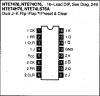
Hi there. Im new to the forums and have a question. Im building a circuit that uses the momentary tactile switch I have as a push on push off button to light up an LED. However the only solution to this I found on Google through just one site found HERE was to use a J-K Flip Flop IC. Now I managed to score some off of RadioShack.com, only the ICs I purchased are NTE74H76, which are 5v J-K Flip Flop IC with Preset/Clear. I also managed to download the PDF to what each of the pins do off the IC chip. I followed the instructions the site gave, but the only difference was I have my 9v battery running through a 7805 voltage regulator to drop the voltage down to 5v, run it all through the breadboard, and....the LED just stays on no matter what, even if I output it from Q or /Q. Heres how I wired it:
The LED Im using is Blue with a Vf of 3.7, at 20 mA, and 2600 mcd.
The momentary tactile switch I have has 4 legs, with 2 (+) on top and 2 (-) on the bottom
- I have the (+) of the 9v battery hooked to the 7805 voltage regulators left pin for input.
- The middle pin of the 7805 is ground, and is hooked into the (-) of the 9v battery.
- The right pin of the 7805 is outputing 5v and being fed into the bread board.
- The ground is also connected to the bread board as well as the (-) of the 9v battery.
- I wired the bread board so power and ground is fed through both the top and bottom of the bread board.
- 5v DC is being fed into the NTE74H76 IC chip where it says VCC.
- The IC chip is also grounded where it says GND.
- 5v is also being put into one of the two (+) of the 4 legged momentary tactile switch.
- The (-) end of the momentary tactile switch is connected to the CLK of the IC.
- A 10k ohm resistor has been placed at J of the IC and is connected to 5v so it is High.
- A 10k ohm resistor has been placed at K of the IC and is connected to 5v so it is High.
- A wire has been placed on PR (Preset) of the IC and is connected to ground.
- A wire has been placed on CLR (Clear) of the IC and is connected to ground.
- A wire has been placed on Q and is connected to a 65 Ohm resistor. This is the output of the chip.
- The 65 Ohm resistor has been connected to the (+) of the blue LED.
- The (-) of the LED is connected to ground.
Power it up and it stays on no matter what. After repeatedly pushing the button, it still stayed on. No flicker or anything. And like I said I even tried wiring it to /Q as the output but same thing happened. Here is a pic of the chip Im using. What could I be doing wrong? Thanks in advance and let me know if you need more details or pics.