I'm trying to use a Sziklai Pair of transistors to discharge a battery to a precise voltage. Regardless of the ongoing debate on the "memory effect" afflicting NiMH batteries, there are a other situations where it's desirable to perform a discharge cycle to 1.0 or 0.9v on a NiMH cell. In my case, my NiMH charger only charges in pairs but I don't always use my cells in pairs; in such a scenario, one cell will get undercharged and the other will get overcharged. By discharging both to exactly the same state, I can then charge them evenly and thus extend cell lifetime.
**broken link removed**
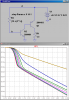
The idea is at any battery voltage above 1.0, R2 allows the NiMH battery to discharge at .5C (1A for AA, or 400mA for AAA). As soon as voltage falls to 1.0v, R1 will cause T1's base voltage to fall below its natural 0.7v cutoff which switches off T2 and the battery experiences no further drain (over-discharging NiMHs cells seriously damages them or else I could do this with only a resistor!).
I have not built this circuit yet but I'm trying to simulate it in software and I'm not getting the desired result. Could just be I don't know how to run the software right but either way I'd like some input on the above circuit because it seems the Sziklai Pair is shutting down the current (green) at about 1.2v (blue) no matter what value R1 is given? I guess what I'm looking for is a "knob" to adjust the voltage cutoff point for the Pair and R1 isn't doing it (at least, in simulation):
**broken link removed**
I am admittedly a semiconductor noob so I suspect this is just me being dumb with either my design or my simulator (or both)?
Input welcome. Thanks in advance!!
**broken link removed**
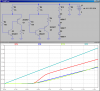
The idea is at any battery voltage above 1.0, R2 allows the NiMH battery to discharge at .5C (1A for AA, or 400mA for AAA). As soon as voltage falls to 1.0v, R1 will cause T1's base voltage to fall below its natural 0.7v cutoff which switches off T2 and the battery experiences no further drain (over-discharging NiMHs cells seriously damages them or else I could do this with only a resistor!).
I have not built this circuit yet but I'm trying to simulate it in software and I'm not getting the desired result. Could just be I don't know how to run the software right but either way I'd like some input on the above circuit because it seems the Sziklai Pair is shutting down the current (green) at about 1.2v (blue) no matter what value R1 is given? I guess what I'm looking for is a "knob" to adjust the voltage cutoff point for the Pair and R1 isn't doing it (at least, in simulation):
**broken link removed**
I am admittedly a semiconductor noob so I suspect this is just me being dumb with either my design or my simulator (or both)?
Input welcome. Thanks in advance!!