Continue to Site

Welcome to our site!

Electro Tech is an online community (with over 170,000 members) who enjoy talking about and building electronic circuits, projects and gadgets. To participate you need to register. Registration is free. Click here to register now.

  • Welcome to our site! Electro Tech is an online community (with over 170,000 members) who enjoy talking about and building electronic circuits, projects and gadgets. To participate you need to register. Registration is free. Click here to register now.

SWR Watt Meter Problem

Status
Not open for further replies.

Suraj143

Active Member
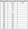
I want to design a PIC based SWR watt meter. Please see the attached block diagram of our system.My main problem is the Low Pass Filter Out gives different voltages at different PLL frequency.

Ex:if we tuned 90.2Mhz/200Watts the voltage out is somewhat
if we tuned 103.2Mhz/200Watts the voltage out is somewhat.

The voltage is varying to tuned frequency.How to overcome this?

Also attached our filter coupler.
**broken link removed**
 

Attachments

  • RF Amp.JPG
    RF Amp.JPG
    59.6 KB · Views: 127
Your EBAY.COM filter has almost no data.
The ones I made are tune-able. I think your filter is reducing the carrier at the high end of the FM band. I think you need to push the filter frequency up a little.

Are you driving an antenna or a dummy load? It could be the antenna is tuned low.
 
Last edited:
Your EBAY.COM filter has almost no data.
The ones I made are tune-able. I think your filter is reducing the carrier at the high end of the FM band. I think you need to push the filter frequency up a little.

Are you driving an antenna or a dummy load? It could be the antenna is tuned low.

You got it.I'm driving an antenna.The "Bird" brand analog meter which is connect before the antenna is showing correct wattage.The problem is low pass filter analog out shows different voltages to different tuned frequency.

I have attached the checked voltages.
 

Attachments

  • voltage vs F.PNG
    voltage vs F.PNG
    8.3 KB · Views: 112
The antenna is not 50 ohms at all frequencies. So you might be driving 50 ohms at 88mhz and 75 ohms at 108mhz.

If you remove the filter; how are your readings? Are they good from 88 to 108? I am trying to find where the problem is. Because I am not there with you it is hard.
 
I see your meter comes from the filter.
You are measuring forward voltage. What happens to reverse voltage? 88 and 108mhz
 
I have never had a antenna that could go from 88 to 108 with out tuning. or a transmitter that did not need tuning. but I had high power.
So if antenna is good and transmitter is good. Probably coax is good. So it must be the filter.

I would spread the wires in the coil a small amount to push the cut off frequency up. This is dangerous because you could brake something.
 
Status
Not open for further replies.

Latest threads

New Articles From Microcontroller Tips

Back
Top