Continue to Site

Welcome to our site!

Electro Tech is an online community (with over 170,000 members) who enjoy talking about and building electronic circuits, projects and gadgets. To participate you need to register. Registration is free. Click here to register now.

  • Welcome to our site! Electro Tech is an online community (with over 170,000 members) who enjoy talking about and building electronic circuits, projects and gadgets. To participate you need to register. Registration is free. Click here to register now.

Switching LEDs

Status
Not open for further replies.

skeeterb

Member
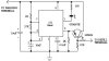
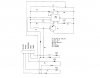
This circuit is a portion of the circuit that I am working on, as many could tell, but I have changed my ideas for the operation of the indicator circuit as I call it. I want the Warning LED (Orange) to burn steady until the cell starts refilling, then I want the warning LED to flash until the pump switches off and the cell resumes operation. I plan on using a 555 circuit to make it flash, but my problem lies in switching it from steady burn to flashing using the 555 circuit. I've done started looking at the 555 Circuits that I can use for this purpose. What kind of setup would I use to switch from steady burn to flashing using the 555 circuit? :confused: Thanks for any help y'all can give me. I have attached the current circuit diagram for what it is now.
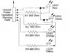
 

Attachments

  • Indicator.JPG
    Indicator.JPG
    76.5 KB · Views: 211
If you connect the red LED circuit between the supply voltage and pin 3 of the 555 timer. That is the resistor LED combination with the anode side of the LED to the supply voltage and the cathode side to pin 3 of the astable configured 555, the red LED will flash. Then if you ground pin 4 of the 555 the LED will go on steady.
 
I didn't think of that, but I want the Red LED to burn steady and the Orange LED to flash when the Red LED comes on, but burn steady until the Red LED is turned on. That's what I'm asking. I don't want to mess with PICs right now, that's still above my level of experience in working with electronic circuitry.
 
It's not that. I feel that I'm not up to that level of experience to use microcontrollers yet. I'm still struggling in the minors or working on fairly low level electronics.
 
Not so tough really, you can even practice for free with MPLAB and its simulator.
Blinking lights is something the PIC does very well, and could hook directly to your diagram at the top of this thread.
 
I'm gonna stick with some less difficult electronics, because I have little experience with programming, and don't want to get into that until I want to create a more complicated circuit.
 
skeeterb said:
I'm gonna stick with some less difficult electronics, because I have little experience with programming, and don't want to get into that until I want to create a more complicated circuit.
What is the voltage in your circuit that is feeding the LED's.?
 
k7elp60 said:
What is the voltage in your circuit that is feeding the LED's.?

the entire circuit is run by 12VDC. That's the control circuit and the indicator circuit. I'm sorry I didn't indicate that when I copy and pasted it from my original circuit. All I need is to switch the Warn (Orange) to burn steady while the Refill LED is off and flash when the Refill (Yellow) turns on. I've been looking at different transistors and FETs that I may be able to use, but don't know what to use.
 
Last edited:
skeeterb said:
the entire circuit is run by 12VDC. That's the control circuit and the indicator circuit. I'm sorry I didn't indicate that when I copy and pasted it from my original circuit. All I need is to switch the Warn (Orange) to burn steady while the Refill LED is off and flash when the Refill (Yellow) turns on. I've been looking at different transistors and FETs that I may be able to use, but don't know what to use.
Well it is possible to just add a flashing LED to the circuit. There are LED's that have the flashing circuitry built in. The flash rate varies a little but as I recall it is about 2 times a second.
 
hrmm, I didn't think about that, but like I said I only want it to flash when the HHO cell is refilling, but burn steady until the pump kicks in.
 
you're going to need a small pile of logic and analog chips to pull this off, or one microcontroller.

I understand that it seems like there is a lot to learn with microcontrollers, but I don't agree that it's all necessary. Check out the picaxe chips ... they're inexpensive, require no special programmer at all, and have a free easy to use (designed for grade school kids) programming language. you'll have to use a little "glue logic" to interface your various inputs with the chip but it'll still be a lot easier than cobbling something together out of discrete logic and analog circuits.
 
I may just have to leave it where it only burns steady, instead of making it flash. I hate that I won't get to make that idea work like I wanted it to.
 
skeeterb said:
hrmm, I didn't think about that, but like I said I only want it to flash when the HHO cell is refilling, but burn steady until the pump kicks in.
I still think we can do it with out a lot of circuitry. If the Refill terminal has no voltage until the yellow LED is turned on and the warning terminal has 12V when you want the orange LED operate on both conditions(flashing/not flashing) it can be done two ways one with a 555 timer and an additional transistor(NPN). The other way is with a flashing LED and two transistors(1 NPN and 1 PNP). Both circuits would require a few extra parts but no additional IC's
I am going out of town for 2 days so I'll check when I get back.
As a side note: If the Power,Operation,Warning and Refill terminals have either no voltage or +12V with respect to ground the diodes connected to each LED is not necessary.
 
k7elp60 said:
I still think we can do it with out a lot of circuitry. If the Refill terminal has no voltage until the yellow LED is turned on and the warning terminal has 12V when you want the orange LED operate on both conditions(flashing/not flashing) it can be done two ways one with a 555 timer and an additional transistor(NPN). The other way is with a flashing LED and two transistors(1 NPN and 1 PNP). Both circuits would require a few extra parts but no additional IC's
I am going out of town for 2 days so I'll check when I get back.
As a side note: If the Power,Operation,Warning and Refill terminals have either no voltage or +12V with respect to ground the diodes connected to each LED is not necessary.

That's mainly what I was thinking about, using transisitors and an ASTABLE 555 circuit to make the LED flash when the REFILL LED is lit and burn stable when the REFILL LED is off. the Power LED is lit while the entire system is turned on, the Operation LED is only lit when the the pump is off, the valves are closed and the PWM and recirculation pump are running. When the water level gets below the Upper Water Level Sensor, the WARN LED lights up and burns steady, until the water level gets below the Lower Water Level Sensor and the REFILL LED is lit, the PWM off , the recirculation pumps off, the refill valve open, and the refill pump on.
 
Last edited:
Here is the circuit I came up with. Hope this helps
 

Attachments

  • 555 FLASHER.JPG
    555 FLASHER.JPG
    17.8 KB · Views: 180
Thanks for your help man. I posted the other part of the circuit that this circuit is a part of. I'm not sure of it put see what you think. https://www.electro-tech-online.com/threads/circuit-help.35261/.
Like I said to RadioRon I'm a NOOB when it comes to designing circuit diagrams. That circuit was really my first attempt at designing a circuit. And to think it started with me messing around with some wires and relays that come off of buses when my step-dad/Boss changes the motors on the Crossing gates on a school bus.


Edit: I've completed this portion of the circuit, now all I have to do is do a copy and paste of this circuit onto my control circuit drawing and the circuit will be completely finished.
 

Attachments

  • Indicator Circuit.jpg
    Indicator Circuit.jpg
    267.3 KB · Views: 381
Last edited:
Status
Not open for further replies.

Latest threads

New Articles From Microcontroller Tips

Back
Top