Continue to Site

Welcome to our site!

Electro Tech is an online community (with over 170,000 members) who enjoy talking about and building electronic circuits, projects and gadgets. To participate you need to register. Registration is free. Click here to register now.

  • Welcome to our site! Electro Tech is an online community (with over 170,000 members) who enjoy talking about and building electronic circuits, projects and gadgets. To participate you need to register. Registration is free. Click here to register now.

Switching Led

Status
Not open for further replies.
Hi Kiss,
My scope has no invert, I tried what you mentioned.
Please see pictures attached.

Can I make a current probe somehow?

Maybe I can use a Lissajous pattern?

Cheers
 

Attachments

  • Scope 1.jpg
    Scope 1.jpg
    88.2 KB · Views: 121
  • Scope 2.jpg
    Scope 2.jpg
    90.5 KB · Views: 105
OK. It has add and subtract, but no invert. Most scopes have invert. So, you usually do an invert and add which apparently is more versatile. Subtract teaches you "What to think" and not "How to think".

Oh well.

The only real way of handling it, is a voltage divider across the 6 ohm resistor and an inverting amplifier (Gain=-1). e.g. +-12 V supplies and a divider that reduces the secondary voltage to less than +-10 V p-p maximum. Then a protection resistor so the OP-AMP doesn't blow up when it's unpowered.

No big deal to put together.

In the short run, you really should be looking at just the voltage across the transformer / load (RC combo)

Actually, why not try to look at:
The full secondary voltage and
The voltage across the resistor which is current.

The above makes a lot more sense. Everything would be in phase and you would be looking at the voltage and the current like we're supposed to.

Then adjust the gains using both the variable and fixed such that the p-p amplitude are the same on the screen.

Sorry, I misled you.
 
Last edited:
Hi Kiss,
I just posted this to make sure it is what you mentioned but then noticed your addition to the other post which I will read now.
Did I have it right anyway?
Cheers
 

Attachments

  • Circuit Mentioned.PNG
    Circuit Mentioned.PNG
    31.1 KB · Views: 121
Close, but IGNORE the idea. 20/20 hindsight says it doesn't make sense to use it.

Just ground the side of the resistor connected to the transformer.
Put probe A so it's across the secondary.
Put probe B across the resistor.

That will give a voltage proportional to the current through the RC network and the voltage across the RC network. That's what we want.
 
Hi Kiss,
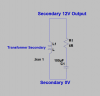
This is where I get a little confused, you mention to "ground the side of the resistor connected to the transformer".
As I see it I have no ground to connect to?
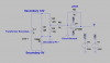
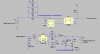
All I have is an Active & a Neutral connection on the Primary side & a 12v & a 0V connection on the Secondary side, sorry for my ignorance?
I have attached a picture of the connections I have, could you please elaborate on how to connect this for the proper readings we require.

Another Question:
Obviously I am missing something here that doesn't seem to compute.
The Triac is controlling the Primary side of the Transformer & the primary side has Inductance, Resistance, Inductive Reactance etc.
So how does testing the Current Lag or phase difference on the Secondary Side relate to how the Triac controls the Primary side of the Transformer. Obviously the secondary side has different Inductance etc etc.
Does not the Primary side of the transformer create the issues I am having with the Triac at the moment?

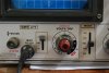
I tried forcing the Triac off in the software, I have it now so when the Pot to the Arduino is totally OFF there is no gate pulse going to the Triac, you can see this on the Scope.
Unfortunately the Triac is still on or being triggered on by something else still & there is still around 120V output from the Triac.

Cheers
 

Attachments

  • Secondary Connection.PNG
    Secondary Connection.PNG
    13.2 KB · Views: 116
What Triac are you using again. Link to the datasheet.

==

Add a resistive minimum load of 50 to 100 mA to the primary.

==

Check for the 0V output when forced to zero.

===========================================================================================

Your right, but for arguments sake:

Swap R1 and C1 on your diagram.

Ground the 0V side. meaning the scope sees this as ground.
One probe across R1
Another on the 12 V point in your diagram.

==

Your correct: the triac in the primary will be different than a triac in the secondary. A triac in the secondary might be the right thing to do, but for now leave it as triac in primry and add a minimum resistive load on the primary side. i.e. A resistor across the primary. R=240/0.1. 0.1 A is probably not optimal. Need the datasheet.
==
 
Hi Kiss,

Had some trouble logging into to Forum this morning?

I am using just a BTA16 600B for this testing at the moment Data Sheet here:
https://pdf1.alldatasheet.com/datasheet-pdf/view/22033/STMICROELECTRONICS/BTA16-600B.html

The BTA16 Triacs I have may be cheap copies as well as the ST marking on them is not good, they have been working ok for the manual control of the Universal Motors so far.

I Have some NXP BT151 500 as well that look original:
https://pdf1.alldatasheet.com/datasheet-pdf/view/16805/PHILIPS/BT151-500.html

The Triacs I purchased for the Universal Motor control when ready are NT 56033. I may have chosen wrongly with these though, if so I will buy what is needed?
https://pdf1.alldatasheet.com/datasheet-pdf/view/10470/NTE/NTE56033.html

I'll try a couple of things until I here back from you.

Cheers
 
I added a variable resistor 50W across the primary with .104A load applied to it.
It has made it slightly better, it now has NO over voltage condition with the Pot Off but still has 62V Ac at the Triac output with the Pot totally off.
The Triac output gets down to 8v near turn off then jumps to the 62V at turn Off

There is still the instability near turn Off or just On.
My wonderful wife has bought me a video camera to show the problems I am having instead of me trying to explain in my usual incoherent gibberish?

This a very short video 30sec showing the Zero Cross & the Pulse Train to the gate, you will see that near turn Off or just at turn On the instability I am talking about, this will explain better than I can possibly do.
When this happens you can measure the instability at the the Triac output, I do not know but could this be due to the Triac gate not latching correctly & jumping in & out of conduction if that is the correct way to put it?
I hope the moderator doesn't mind due to the circumstances involved?

Cheers
 
Last edited:
I measured the Current lag from the secondary winding as suggested, it is about 5mS between the two signals.
So if I have this correct that works out to be 90deg Lagging, is that correct.

Cheers
 
Try line trigger and use the slope and level controls.

The problem, I think makes some sense to me. The data sheet sucks as a datasheet. The Triac chosen makes it difficult to work with an inductive load. Explaining it will be harder.

70 mA is the minimum load that you need through the Triac. That's why I picked 100 mA.
 
Hi Kiss,
I tried the Line Trigger but with the same results.
I tried a few other things in the software but once you get the pulse to the gate to cease then it is beyond the control of the software, I connected the lamp again & everything works perfectly.

Ok, what type of Triac do I require for this testing of the Transformer & the Universal Motor Controller when I am ready for that, I will see what I can get locally, well 100km's away.
Or are SCR'S better suited to this application?
Should I try the BT151 Triac?

Cheers
 
I was just thinking that the Triac circuit I use for the manual Universal Motor control now does not have a True Zero either, at zero setting of the Pots it always starts the motors at lower rpm when you turn the switch on.
I thought nothing of it before because the rpm was always lower than the required rpm for testing?

Cheers
 
Sorry for all the posts but I think I have just found the problem?

When you mentioned that the minimum load needed to be 70mA I thought that the Primary winding of the Transformer would be adequate enough for the load.
I just checked the DC resistance of the primary of this NEW CHINESE Transformer & I cannot get a reading or a continuity reading either.
I tried three different DMM but it appears to have a bad winding, I get no Inductance reading either.
There is no short to the Core.
So how come the damn thing still works, it still gets warm & adjusts to maximum voltage???????????????????????????????????????????

Cheers
 
Possible causes for primary winding failure:
Inrush Current, Over Voltage like was happening.

How best to protect against primary winding failure again?

Cheers
 
You need a quick math lesson. The definition of Quadrants. See: http://www.math.com/school/subject2/lessons/S2U4L1DP.html

Operating in quadrant I and quadrant III is a resistive load. The I, II, II and IV are roman numerals.

OK, so what does quadrants have to do with Triacs?

When you look at your datasheet:
I am using just a BTA16 600B for this testing at the moment Data Sheet here:
http://pdf1.alldatasheet.com/datasheet-pdf/view/22033/STMICROELECTRONICS/BTA16-600B.html

There is a column labeled quadrant.

In order to operate in Quadrant IV (4), you need twice as much current.

Post your drive circuit.

The thing is, I don't really like the datasheet. It's a complex relationship that I need to brush up on.

There is a Triac called a "sensitive gate triac" too.

Your trigger circuit probably can't dump 100 mA into the gate?
 
This is where VA starts to matter. What were the specs of the transformer?
The secondary load was 100 uf and 100 ohms, I think.
and something like 2400 ohms 50 W on the primary. I didn't expect 24 W.

have fun sorting it out. You've come a log way.
 
Oh no, maths lesson:nailbiting:
Ok i'm in!

There were no specs given for the transformer just 2 Amp Max, there are seven output taps between 12V & 30V, I chose 12V to be safer.
So I guess the VA rating would be 60VA.

The Secondary Load is 100uF & 6Ω Resistor.
The Primary Load is 25W so I used a 50Watt Resistor 2.3K giving approx 104 mA

Yeah, it's a steep learning curve but it is very interesting.

The drive circuit attached, I have a cd40106 after the 4N25 which is not shown.

I'll go through what you have mentioned & get back to you.

I'll get this no matter what!

Forgot to mention the transformer never got hot at any stage, just warm--normal.

Cheers
 

Attachments

  • Drive Circuit.PNG
    Drive Circuit.PNG
    30.6 KB · Views: 118
Hi Kiss,

First up before I go to far on the wrong track, is this how the Quadrants you mention relate to the sine wave?
This is bad you know on a forum showing everybody how much I don't know at my age, it can be nothing but character building.:confused:
I find it's better to draw things with the way my head is these days.

Cheers
 

Attachments

  • Quadrants.PNG
    Quadrants.PNG
    29.3 KB · Views: 122
Status
Not open for further replies.

Latest threads

New Articles From Microcontroller Tips

Back
Top