Continue to Site

Welcome to our site!

Electro Tech is an online community (with over 170,000 members) who enjoy talking about and building electronic circuits, projects and gadgets. To participate you need to register. Registration is free. Click here to register now.

  • Welcome to our site! Electro Tech is an online community (with over 170,000 members) who enjoy talking about and building electronic circuits, projects and gadgets. To participate you need to register. Registration is free. Click here to register now.

Switching A Current Source

Status
Not open for further replies.

dknguyen

Well-Known Member
Most Helpful Member
Hi. I need to modulate an LED using a current source. The LED is part of a solid-state relay that is to switch at 100Hz for the ultrasonic ranger. It's purpose is to disconnect the receiver from the transmitter during transmission otherwise the receiver basically goes deaf (just like a bat). But in order to get the minimum distance I want the switch must connect the receiver to the transducer within 0.5ms. As a result, I need to drive the SSR's LED at 20mA out of a maximum of 25mA. The LED forward voltage also varies by too much so I can't just use a precision resistor value blindly without potentially burning out the relay.

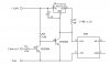
SO I want to use a current source. Basically this one (except it's actually all inside an adjustable voltage regulator)

https://en.wikipedia.org/wiki/Image:Op-amp_current_source_with_pass_transistor.png

and switch the current source on and off. Except that it seems to me that the regulator cannot respond fast enough. If I modulate the enable PIN on the regulator it takes 1ms to turn on (not including the delay of the relay).

So I either have the option to place a MOSFET in series with the LEDand modulate it that way, or play a shunt MOSFET in parallel with LED and modulate it like that. But the series case requires both the amplifier current and voltage output to adjust during switching while the shunt method requires the amplifier voltage output to change (and not so much the current output). Either way, I don't know if any of this will help.

Any ideas?
 
Last edited:
Dkngyen,

We had to do this for a laser diode for one of our senior student's Honors Projects. Constant-current source using a standard three-terminal voltage regulator with a switched shunt to chop the laser output. Attached is a schematic, scaled down to fit your current levels. High control turns the SSR ON, low turns it OFF. If you need the reverse, drop Q1, move R2 to between the base and emitter of Q2, and put R1 between your control input and the base of Q2. The component values are a "mind experiment" and not bench tested (we were using much higher currents), but they should be close enough to start.

Ken
 

Attachments

  • LED Power+Control03.jpg
    LED Power+Control03.jpg
    15 KB · Views: 951
Oh, I kind of see what you did. You may remember me saying earlier how I prefer MOSFETs over BJTs especially for switching. THe only time I ever use BJTs is when for something like a zener regulator or something like that. So what happened when I shunted using a MOSFET is the current levels would change by quite a bit since the voltage drop across the MOSFET was much less than the LED. So the current and voltage levels jumped around quite a bit.

THe way your circuit works is you used another diode as the load? (The B-E diode of the BJT in this case) where it's voltage drop is just a little smaller than the LED so that it shuts off while the current levels stay at a similar point to the LED operating current?

It's also neat to see how current regulators are different inside. WHen making a current source with these two regulators, the positions resistor and load are interchanged because the feedback loop of one feeds to the amp while the other feeds to the to the voltage reference.

EDIT: Nvm about the second paragraph. The LM317 works differently from the REG101A. The load in the current sourcing LM317 is not in the feedback loop like it is with the REG101A so when you shunt the LED current for the LM317 it doesn't there is no dynamic voltage/current change going on for the LM317 like there is with the REG101A.

THanks!
 

Attachments

  • LM317.gif
    LM317.gif
    12.5 KB · Views: 613
  • REG101A.gif
    REG101A.gif
    17.8 KB · Views: 530
Last edited:
The 1uF cap in the LM317 circuit will delay the turn-on of your current source by about 100usec. It will also feed ripple current to your LED if there is any ripple on the LM317 input. I don't see any reason for it to be there. You do need a cap from Vin to GND if your rectifer's filter cap (assuming you have a rectifier) is more than a few inches from the LM317.
EDIT: Q2 diverts the 20+ mA which is supplied by the LM317 away from the LED. The current always flows. You could save a little power by using a current source that switches on and off.
Another edit: You could also power the entire current source off +5V, if that's any benefit.
 
Last edited:
THis is the circuit I made from what KMoff gave me. I don't think the regulators turn on and off fast enough. THe first one I was working with was 1ms to turn on which was my limit. THat's why I thought about a parallel shunt across the LED so the current wouldnt change so the source would not have to react.

So assuming the MOSFET turn off time is negligible and that the current source does not have to react to anything, the LED turn on is about 0.5ms max.

The whole set up spends most of it's time listening anyways so I don't think the wasted shunt current is a problem (lots of power is beign used in other parts of the circuit anyways).
 

Attachments

  • Image1.gif
    Image1.gif
    10.1 KB · Views: 547
Last edited:
dknguyen said:
THis is the circuit I made from what KMoff gave me. I don't think the regulators turn on and off fast enough. THe first one I was working with was 1ms to turn on which was my limit. THat's why I thought about a parallel shunt across the LED so the current wouldnt change so the source would not have to react.

So assuming the MOSFET turn off time is negligible and that the current source does not have to react to anything, the LED turn on is about 0.5ms max.

The whole set up spends most of it's time listening anyways so I don't think the wasted shunt current is a problem (lots of power is beign used in other parts of the circuit anyways).
Your LM317 doesn't have enough headroom. I'm guessing your LED drops about 2V. The 63 ohm resistor drops about 1.25V. That leaves only 1.75V for the LM317. That's just about the typical DO voltage for the LM317L at 20mA. Worst case (spec.) is 3V. I wouldn't be comfortable with 1.75V. You might. :rolleyes:
 
I don't think it's going to be a problem (see attached LED graph for forward voltage). I calculated 2V for the LM317 at worst case everything.
 

Attachments

  • Image1.gif
    Image1.gif
    13.1 KB · Views: 409
dknguyen said:
I don't think it's going to be a problem (see attached LED graph for forward voltage). I calculated a headroom of about 2.25V
Yeah, I looked it up too, after I posted.:( The LED only drops 1.3V. I still would not make a production run with that circuit, but it's probably OK for a one-off. It certainly is simple.:)
 
I could always switch the 5V supply to be 15V. I got a lot of regulators lying around this circuit. It's silly really. The gate driver bootstrap ICs cost just as much as a floating DC-DC converter.
 
Last edited:
How about building a current source with a fast op-amp and switching it?
 
Hero999 said:
How about building a current source with a fast op-amp and switching it?
I thought about that (well not about the fast op-amp part anyways) and ended up choosing a regulator because I thought it would take less resistors and components and be more accurate. I will look into it. RIght now I have the current shunt in my circuit. You are implying that a fast op-amp current source can react faster than a regulator-based current source? I guess the main issue with that is I would not be sure the circuit would be fast enough until I built it.
 
One can build a simple current source using just two BJTs and a couple of resistors. Its good for all practical purposes.
 
Status
Not open for further replies.

Latest threads

Back
Top