Continue to Site

Welcome to our site!

Electro Tech is an online community (with over 170,000 members) who enjoy talking about and building electronic circuits, projects and gadgets. To participate you need to register. Registration is free. Click here to register now.

  • Welcome to our site! Electro Tech is an online community (with over 170,000 members) who enjoy talking about and building electronic circuits, projects and gadgets. To participate you need to register. Registration is free. Click here to register now.

Switching 3V on and off rapidly with minimal waste of power

Status
Not open for further replies.

mik3ca

Member
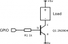
Because my radio module gave me bad luck and the only way I can make it work consistently (instead of intermittent failures) is to turn it off then back on again, I'm thinking of having the microcontroller (powered with 3V) control the power via a typical NPN setup where:

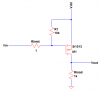
NPN base is connected to micro via a 1K resistor, and the collector is connected to VCC via a 50 or so ohm resistor (which here vcc will be 3V) and emitter is grounded.

I plan to have the radio module's VCC connected to the NPN collector so it gets controlled by the micro.

Yes I'll have to do ohms law to find the correct resistor to allow 120mA to flow through so the module can get all the current it needs, but this method after looking at it seems wasteful because every time the micro shuts power to the radio module off, the resistor from 3V is grounded so I'm basically drawing 120mA for nothing?

I mean I understand the off time will be super short relative to the on time, but that 120mA is alot of current being wasted.

So other than the typical common-emitter amplifier setup to control power, is there another way I could do this?

I even thought of opto-isolation as well but the output side is also a transistor as well.
 
Welcome to ETO!
You could get rid of the 50 Ohm resistor and connect the module between the 3V line and the collector.
 
I plan to have the radio module's VCC connected to the NPN collector so it gets controlled by the micro.

You want to connect the radio's Vcc to the collector??? ??? ??? Do you mean the radio's ground?

Are you trying to do the attached photo? I don't see why you need a 50ohm resistor to begin with.

If so, you could use a PNP or a P-channel MOS on the high-side rather than an NPN or N-channel on the low side so the switch voltage drop doesn't disrupt the ground. Disrupting ground could cause issues in some cases (radio modules could be particularly picky).
 

Attachments

  • Npn_switch.png
    Npn_switch.png
    9.1 KB · Views: 99
Last edited:
Ok I'm adding a circuit because at least somebody is confused:
circuit.png

As you can see, the microcontroller is powered with 3V.

For the purposes of my question, the details of the internal functionality of the micro as well as the wireless data content are irrelevant.

What is known is that one pin of the microcontroller will be made as output and will control when the entire radio module goes on and off.

Yes I am completely aware than an enable input exists as well but because the radio module gives me bad luck (I suspect someone programmed it wrong), I'm going to use every line of that radio module available to me including the power pin.

In this circuit I will be able to turn the module on and off, but the problem is that this circuit wastes alot of current when the microcontroller turns the power to the module off especially with the 50 ohm collector resistor.

If I remember transistor operation, then when the pin feeding the base goes high, then current goes from collector to emitter which means the 50 ohm resistor is connected from VCC to ground which means 3/50ths of an amp of current is wasted for nothing. I want to avoid wasting this current.

Any way I can pull it off? I'm not sure if totem pole could help here. hmm..
 
Well there's your problem. You never don't short across the power pins of something to shut it off. You interrupt the current. Do something more akin to what I showed in my previous post where the switch is in series with the thing you want to power down.

99.999% of the time, never short across the power pins of something to shut it down.
 
My circuit shows no short. I'm just illustrating that VCC is 3V battery +ve (same connection) and GND is the other end of the battery.

I looked at your previous post and based on it, you're suggesting I should connect all VCC's together and all grounds of the module to NPN collector? I mean its an idea but would enough power get into the module? I'm asking for the datasheet limit of 120mA so the module functions normally when on.

The module is HM-TRP
 
Ok for now I'll try the circuit someone posted but using a PNP transistor that way theres common ground for all
 
I looked at your previous post and based on it, you're suggesting I should connect all VCC's together and all grounds of the module to NPN collector? I mean its an idea but would enough power get into the module? I'm asking for the datasheet limit of 120mA so the module functions normally when on.

The module is HM-TRP

Why wouldn't enough power get into the module? Would the circuit make more sense to you if the NPN was replaced with a relay? Same concept.

That said, are you really using a 2N706 transistor? That transistor caps out (saturates) at 30mA. Use a different transistor that doesn't saturate at 120mA.
--------
However, what I actually recommend you to do is to use a high-side P-channel MOS or PNP switch so that the transistor is not in the ground path of the module which could cause issues (like noise or maybe worse for something sensitive like a radio module).

See attached schematic. The resistors are different values of you use a PNP instead of a P-ch but you get the idea. In the PNP/P-ch case, pulling the base/gate LO allows current to flow and turns everything ON while pulling the base/gate HI turns everything OFF.

You can omit R1 if you wish since it's just a pull-up resistor to keep everything off in the absence of a base/gate control signal. The base/gate resistor optional if you are using a PMOSFET, but required if you are using a PNP (obviously don't use 1 ohm for the PNP).

My circuit shows no short. I'm just illustrating that VCC is 3V battery +ve (same connection) and GND is the other end of the battery.
In your schematic, your transistor is connected across the 3.3V and GND pin of the power supply pin. So when the transistor turns on, the module turns off because the transistor starts conducting and produces a short-circuit across the power pins of the module making 0V appear across it. But as you've discovered, it consumes a lot of power because current is essentially flowing directly from the 3.3V rail straight to ground necessistating the 50 ohm resistor.
 

Attachments

  • Figure-1.png
    Figure-1.png
    2.3 KB · Views: 90
Last edited:
I'm actually going to use 2N3905 PNP with the base resistor still in. One datasheet states its current limit is 200mA.
 
I'm actually going to use 2N3905 PNP with the base resistor still in. One datasheet states its current limit is 200mA.
That should do. Remember the control logic is reversed for PNP. Mind the differences in connection for the colletor and emitter compared to the NPN.
 
Status
Not open for further replies.

Latest threads

New Articles From Microcontroller Tips

Back
Top