Continue to Site

Welcome to our site!

Electro Tech is an online community (with over 170,000 members) who enjoy talking about and building electronic circuits, projects and gadgets. To participate you need to register. Registration is free. Click here to register now.

  • Welcome to our site! Electro Tech is an online community (with over 170,000 members) who enjoy talking about and building electronic circuits, projects and gadgets. To participate you need to register. Registration is free. Click here to register now.

Superregen revisited

Status
Not open for further replies.
mstechca said:
If I connected a capacitor between base of the transistor and the point where one end of an inductor, capacitor and the resistor from +ve meet (this capacitor is in parallel with the base resistor carrying the +ve voltage), does this capacitor go in parallel with the capacitor from base to ground when I calculate the capacitance for a low pass filter?

if I am losing you here, I am assuming that a low pass filter is present in the circuit, but the part that is interesting is that I get somewhat better results when I add more capacitors to the circuit.

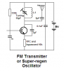
It's hard to say, you've posted a number of circuits, none of which look like they would work?, try posting one with the capacitor you're refering to added.
 
Mstechca,
I don't know why you are changing around all the parts.
The functions of the few parts are clearly explained in the article of the last schematic I posted.
The RFC is not supposed to be a lowpass filter. It is just a high impedance to the RF frequency so that the RF oscillator has more positive feedback through the capacitor from the collector to the emitter, and so that the squegging capacitor does short the RF.
 

Attachments

  • superregen_again.gif
    superregen_again.gif
    11.5 KB · Views: 620
That happens to be one of the most informative answers you posted audioguru.

and why am I changing things around? because I want to try to optimize the circuit for local channel 11 TV station.

Do I take the oscillator capacitors (in blue boxes) and calculate them in parallel or in series?
 
mstechca said:
why am I changing things around? because I want to try to optimize the circuit for local channel 11 TV station.
We don't know which circuit you are modifying, but the circuit that I posted can go as high as 174MHz with its tuning capacitor set to minimum and the L1 "half-turn coil" squeezed for minimum inductance. Its 2N3904 "audio" transistor hardly has any gain above 200MHz. So you need less inductance and/or less capacitance and also might need an RF transistor to reach channel 11's 203.75MHz audio carrier. Changing the parts around won't do it.

Do I take the oscillator capacitors (in blue boxes) and calculate them in parallel or in series?
It should be obvious that L1 and the tuning cap are in parallel. I think part of the 7pF cap and the transistor's capacitance are also in parallel with them.
As we explained before, you can't possibly calculate the tiny values for the "coil" and trimmer capacitor because of high stray inductance and capacitance.
 
I'm using the 2N3563 NPN transistor. It can go up to 600Mhz.
 
Mstechca,
Are you talking about the circuit I recently posted?
Did you build it with a tight layout on a pcb?
A 2N3563 has much lower capacitance than a 2N3904 that was spec'd for this circuit. Therefore the value of the 7pF feedback cap probably must be increased for it to oscillate in this circuit. Try 10pF, 12pF or 15pF.
 
**broken link removed**

After literally experimenting with this design, I can guess that the following is correct:

L1 and the 15pF tuning capacitor form a low pass filter.
RFC, 7pF and the 15pF form a colpitts oscillator.

as for the section labelled as "better audio", I tend to ignore that because I don't know what value of capacitor to use, and why it optimizes the circuit.
 
mstechca said:
L1 and the 15pF tuning capacitor form a low pass filter.
No. Read the article again, its operation is clearly explained.
The circuit is a standard simple FM transmitter with L1 and the tuning capacitor in parallel! The 0.1uF supply bypass capacitor makes the supply voltage exactly the same as ground to RF. It oscillates at the RF with positive feedback from the 7pF capacitor.

RFC, 7pF and the 15pF form a colpitts oscillator.
No. As explained in the article, the 0.001uF capacitor and the 10k resistor make the transistor an ultrasonic RC squegging oscillator. The RFC is a high impedance to RF and keeps the 0.001uF cap from shorting the emitter's RF to ground.
The cap is charged with a DC voltage by the transistor beginning to oscillate. When its voltage gets high enough then the transistor can't oscillate anymore and the cap discharges into the 10k resistor until the transistor begins to conduct and begin oscillating again. :roll:
 

Attachments

  • fm_transmitter.png
    fm_transmitter.png
    8.2 KB · Views: 548
I dont understand. When I change the feedback capacitor, the frequency changes. so somehow, that capacitor (even though it appears to be a feedback) must enter into the frequency equation.
 
mstechca said:
I dont understand. When I change the feedback capacitor, the frequency changes. so somehow, that capacitor (even though it appears to be a feedback) must enter into the frequency equation.

We've told you repeatedly! - most of the components in these crude designs will affect the frequency - the feedback capacitor certainly well, as it connects to the tuned circuit.

If you put your hand near the circuit it will change frequency, so altering values actually connected to it are bound to!.
 
The FM transmitter circuit produces FM (its frequency is modulated) by the modulation changing the conduction of the transistor. When the conduction changes, the collector-emitter voltage also changes, changing the collector-emitter capacitance and producing FM. The feedback capacitor is in parallel with the collector-emitter capacitance so it also changes the frequency of the oscillator.
Changing the supply voltage or the temperature of the transistor will also change the frequency in such a simple circuit. :roll:
 
We've told you repeatedly! - most of the components in these crude designs will affect the frequency - the feedback capacitor certainly well, as it connects to the tuned circuit.

If you put your hand near the circuit it will change frequency, so altering values actually connected to it are bound to!.
Well, I can understand that, but there isn't an official equation that determines the frequency?

Even if it involves looking at internal transistor capacitances, I still need an equation.

Audioguru, my design is basically the opposite. My collector and emitter are switched and I use the 2N3563 transistor. It seems that if my feedback capacitor value is too high the oscillation won't work. If the capacitor in parallel with the inductor is too low, then the oscillation wont work again. So somehow, there has to be a valid range for the capacitors and inductors, and I can't determine it. That is why I am looking for an equation.
 
An equation is useless without somehow measuring and including the circuit's stray capacitance and inductance.

I can't see how an oscillator will work with your transistor's collector and emitter switched. Why did you connect it backwards?
 
If I don't then I think I will have to add an extra transistor before the audio amplification stage. If you can show me your version of a completed superregen, I might switch to that.
 
I'm not going to design nor make a super-regen, it isn't a real radio. :cry:
 
audioguru said:
I'm not going to design nor make a super-regen, it isn't a real radio. :cry:

Yes, it's a just a waste of time for a poorly performing device. Super regen's were popular construction items back in the 1960's, when a single transistor was extremely expensive - so it made sense to try and use only one of them!. In the 21st century there's no justification any more, particularly with the much greater number of stations transmitting - a super regen just isn't up to it!.
 
Status
Not open for further replies.

Latest threads

Back
Top