John Dolan
New Member
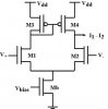
As part of a broader project, I am designing IC circuit using CMOS to one of the first steps I'm working on is the filtering a series of pulses with of the noise. The actual pulses are around 1 kHz so I am implementing 2nd order sallen-key high pass filter. Since the capacitance is limited to 1pF, the resistors in the circuit are instead replaced with a subthreshold transconductance amplifier (differential pair with a PMOS current mirror driving I1 & I2 - see attached picture). From my theoretical knowledge, Gm is driven by the bias current (Ib=I1+I2), which means I need around the 1 - 3 nA range ballpark and I'm not sure how to obtain these. How do I choose the specific bias voltage or transistor sizes to obtain the desired Ib? (as mentioned earlier, these are in subtrhreshold region i.e. vgs <= vthreshold). Any advice is greatly appreciated. Thanks!