Continue to Site

Welcome to our site!

Electro Tech is an online community (with over 170,000 members) who enjoy talking about and building electronic circuits, projects and gadgets. To participate you need to register. Registration is free. Click here to register now.

  • Welcome to our site! Electro Tech is an online community (with over 170,000 members) who enjoy talking about and building electronic circuits, projects and gadgets. To participate you need to register. Registration is free. Click here to register now.

Strobe circuit controlling Pmos gate??

Status
Not open for further replies.
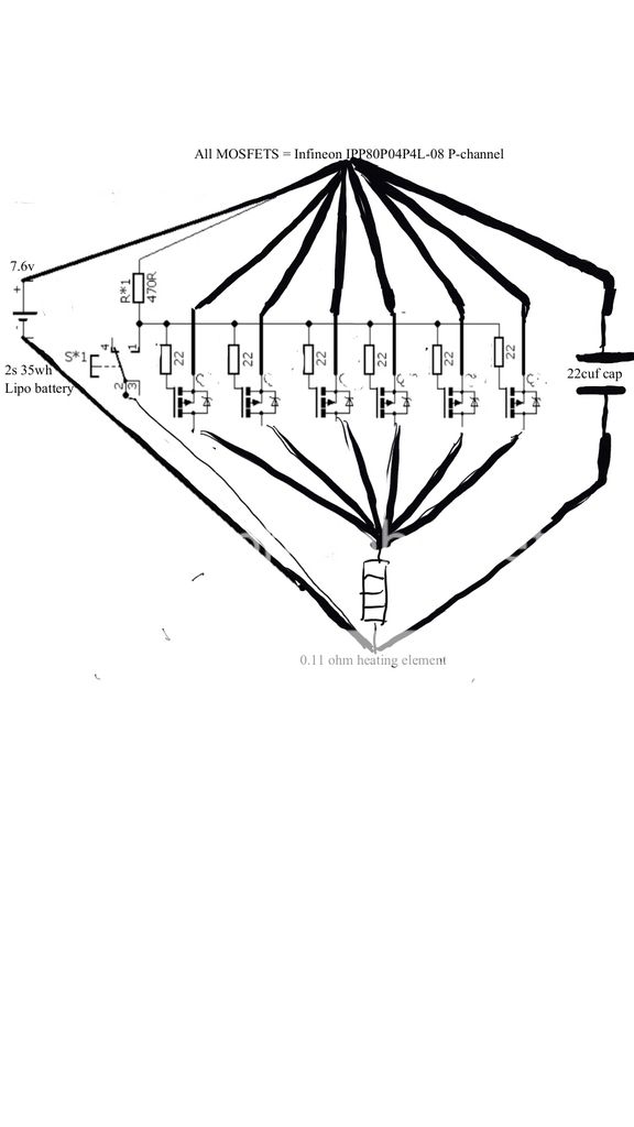
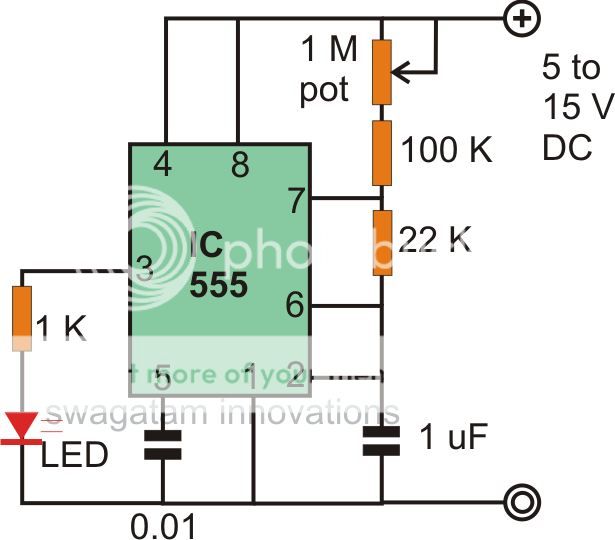
I'm playing with the idea of using a 555 strobe circuit to manipulate the gate on this circuit.. will this work? The effect I'm looking for is upon pressing the momentary switch, power to the heating element is pulsed at a variable frequency (1m pot? ), from just full 'on' down to one pulse every ~2/3 of a second. Can I achieve this?

Note280217_1_zpsolipgwfc.jpg
f149dbce8308cab5de03978b6d8380ec6ee022f8_orig_zps3bwkolvz.jpg


As always, any help with this will be appreciated, I've been down the Google hole for two days now and came up with nothing I understand :(
 
Last edited:
The output pin 3 of a 555 pulses high but your P-channel Mosfets need pulses that go low.
 
O.. k.. so your ruling out a 555 or just pin 3? (Yeah, I've no clue how they work :sorry:)

If that idea is ruled out then is there another way, dual transistor method maybe?
proxy_zpsivdophiz.jpeg
Though I haven't found a way to do it with a pot to control frequency, even if I did I don't know how to add it to my circuit.. every strobe circuit I've seen will have its own resistance so I'm not sure what impact it'll have placed after the 470r on my diagram, for that matter if it's placed before whether the frequency will be altered by there being another resistor o_O

Just so I'm clear, the idea is sound that rapid open and close on the gate is possible at the frequency I desire? The mosfet are capible of doing that right? If not then I really need to stop looking for an applicable schematic because my brain hurts! Haha
 
The P-channel Mosfets use a low input voltage pulses to turn on but the output of a 555 is high output voltage pulses so simply change the Mosfets to N-channel and connect the load to the positive supply or add an inverter transistor to the output of the 555 so that it produces low voltage pulses.

Now you show a transistor multivibrator that destroys the base-emitter of the transistors when the supply voltage is more than about 7V unless protection diodes are added.
 
Although I will be working on an N channel variation of the circuit (https://www.electro-tech-online.com/threads/nmos-circuit-for-heating-element.150320/#post-1289229) this particular one must be P channel. It's also a little too late to change now as I've started it haha
20170310_153252_zpsjar1favu.jpg


I'm limited for space In my enclosure so I attached strobe circuits I've found that I could make and that will actually fit, I'll openly admit I've no clue if they're suitable audioguru, electronics is a very new hobby to me.
 
I do not know why you posted the schematics of a 555 oscillator and a two-transistors multivibrator. Will one of them replace the switch?
The 470 ohm resistor turns off the p-channel Mosfets.
 
Try this circuit. Audio is confused about how a 555 works.

The pulse width is always ~2.5ms, while the duty cycle can be varied from ~1% to ~96%, so should provide smooth control of the heating:
22max.png 23min.png
 
I'm not sure if I asked the question wrongly audioguru. I need the switch, I just wanted to effectively strobe the circuit on and off at an very fast rate once I press said switch.

@MikeMI. I think you've just given me exactly what I was looking for!:woot: I can't tell you how much time I've spent trying to plan that circuit. Now indebted I feel cheeky asking but.. is it possible to add a switch to isolate the 555 side of things so it reverts back to my original circuit if I need it to? A multifunctional aspect to my device would be legendary!
 
...
@MikeMI. I think you've just given me exactly what I was looking for!:woot: I can't tell you how much time I've spent trying to plan that circuit. Now indebted I feel cheeky asking but.. is it possible to add a switch to isolate the 555 side of things so it reverts back to my original circuit if I need it to? A multifunctional aspect to my device would be legendary!

Since I gave you a circuit that could vary the power from 1% to 96%, why not just put a form A switch to break the wire as shown below.With the switch open, the circuit draws a few uA of leakage through the fets. With the switch closed the pulse width is adjustable over the full range. The switch rating only needs to be <1A. You could use a pot with an integral rotary switch.

23s.png
 
Last edited:
You never said that you wanted to vary the amount of heat using Pulse-Width-Modulation.
Instead you wanted to turn the heater on and off with the switch and have a completely separate 555 blink an LED.
 
Ah, sorry audioguru. I guess knowing the correct terms helps when asking for help. My bad :(

I was looking at putting a switch on that section there Mike, breaking the same link to the 555 and diverting the one running underneath parallel (after the 470) to ground.. but yours is way better :joyful: I love simple.

So much thanks I can't express!!
 
Status
Not open for further replies.

Latest threads

New Articles From Microcontroller Tips

Back
Top