micael
New Member
Hi
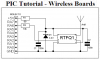
"Never place a Transmitter or Receiver directly into Vero-Board or any similar prototyping board. This will severely restrict the range. Rather, use small lengths of wire from the prototyping board to the pins of the Transmitter or Receiver."
The question is were to put the transmitter or receiver modules and their antenna??
Why the stripboard's capacitance between adjacent tracks affects so much(reduced) the received signal from 17.3 wire antenna placed on a striboard?