Continue to Site

Welcome to our site!

Electro Tech is an online community (with over 170,000 members) who enjoy talking about and building electronic circuits, projects and gadgets. To participate you need to register. Registration is free. Click here to register now.

  • Welcome to our site! Electro Tech is an online community (with over 170,000 members) who enjoy talking about and building electronic circuits, projects and gadgets. To participate you need to register. Registration is free. Click here to register now.

stereo to mono problem

Status
Not open for further replies.
Hello, i am trying to convert stereo into mono on my bluetooth amplifier/receiver, since i am using a woofer + tweeter setup. I included a picture of how i solder the pins together. Right now the pot is up to a maximum, which means the pins are effectively shorted together. I know ur supposed to use a resistor but i am looking for a max SPL, even if the amplifier dies after a few months. The amplifier chip itself is TPA3116D2. The amplifier board is ZK-502C hifi.

Problem 1: Even when the pins are shorted together, i get on average about 4-5dB less SPL than i would otherwise and i dont understand why since i am not using any resistors and pot doesnt offer any resistance.

Problem 2: When pins are shorted together, the speaker amplifier will shut down and restart if the pot is over 80% volume. This happens even if the speakers are not connected ! I am really wondering why.

Question: Is there any way to get around this since i need every single last dB i can get, so i cant lose even 1dB, let alone 3dB.
 

Attachments

  • IMG_1582.JPG
    IMG_1582.JPG
    361.1 KB · Views: 254
  • TPA3116D2-50W50W-Speaker-Audio-Amplifier-with-Filter-HIFI-Level-20-Stereo-bluetooth-Digital-P...jpeg
    TPA3116D2-50W50W-Speaker-Audio-Amplifier-with-Filter-HIFI-Level-20-Stereo-bluetooth-Digital-P...jpeg
    361.1 KB · Views: 234
  • ZK-502C-HIFI-Wireless-Bluetooth-5-0-TPA3116-Digital-Power-Audio-Amplifier-board-TPA3116D2-50WX...jpg
    ZK-502C-HIFI-Wireless-Bluetooth-5-0-TPA3116-Digital-Power-Audio-Amplifier-board-TPA3116D2-50WX...jpg
    212.3 KB · Views: 226
I'd guess the bluetooth IC is intended for a headphone receiver module and includes its own small power amps.

Shorting the pot shorts the amp outputs and overloads them, making it shut down.

Also, combining both channels attenuates any sound that is mostly on one channel, so less overall volume.

The original idea of adding series resistors to each channel where they connect to the pot was to prevent overloading anything.

What values are R12 and R13, near the TPA3116D2? They appear to be connected to pin 8 and if so set the internal gain of the power amp. See page 14 of the TPA3116D2 datasheet.
If that is not using the highest gain setting, you may be able to change those to compensate for proper resistor mixing at the pot?

I managed to get a screengrab from a youtube review, but it's not quite sharp enough to read the resistor values..

ZK502C_TPA3116.png


As the board has an aux in socket which presumably has break contacts to disconnect the BT audio, you could also use the socket connections to intercept the BT audio and add a mixer / amp stage, to combine the channels and give a volume boost???

The real solution is to make the whole thing fully stereo, though.
 
The resistors are 100K and 39K. I went through the datasheet and that is way out of my league, i have no electronic/mechanic background, learning as i go. It would appear that if i change 100K and 39K to 47K and 75K, i will gain another 4dB. It notes that now i have 15K input impedance and i should change it to 9K but i cant seem to find where this resistor is located, maybe you can help me out ?


I did some of my own research into the disconecting problem when mono is bridged with no resistor. It turns out that the pot even when turned all the way on still has about 2.4 ohm resistance. This remains the same whether amp is turned on or off. When i bridge the L and R, i still get the 2.4 ohm, but when i power on the amp, this jumps to 4.9 ohm. When i connect to bluetooth with mobile phone, it drops to 2.4 ohm again. And when i start playing it jumps to 4.9 ohm again. And when i am playing music with bridged pins, when the loud part comes, resistance will rapidly change between 0 and 5 ohms, and it appears when it comes to 0 ohms, the amplifier shuts down and restarts. I was able to solve this by turning the pot down until i changed 2.4/4.9 ohms to 4.5/8.5 ohms. I will need to test how much this affects SPL.
 

Attachments

  • scheme1.JPG
    scheme1.JPG
    117 KB · Views: 272
  • scheme2.JPG
    scheme2.JPG
    143.9 KB · Views: 216
  • 20220901_162356.jpg
    20220901_162356.jpg
    1.4 MB · Views: 231
Yep, changing those resistors would give you 4db more gain.

Th input impedance relates to the internal function of the amp IC and you do not need to change anything because of that.

You cannot measure resistance using the resistance range of a multimeter in a powered-on circuit.
The meter tries to put a known current through the leads and measure the resulting voltage, which for any set current is proportional to resistance.

That only works if the thing you are testing does not have any voltages present....


If you want the maximum power out, why not configure the IC for mono mode? Page 24 of the data.
The left input caps appear to be the two just below the gain resistors, C28 & C29; remove those and link both right ends (nearest the 3116) to ground, then parallel the outputs as in the diagram.

100W, with an adequate power supply..

ZK502C_TPA3116.png
 
Its that simple to make it mono ? That would be wonderful. If i do this plus replace the resistors, i can have both SPL and good audio quality (mono). I will try it !! But before that i have a big problem. I glued the heatsink directly to the amplifier (and bluetooth) chip using bison 5 minute epoxy 2 component glue. What i have at home is heatgun, solder iron, acetone and isopropanol. The amplifier is supposed to have a heat protection at 150C, so i could try to heat to that point and see if it moves. As for acetone and isopropanol, it will be hard to get it between chip and heatsink, and im afraid i might damage the board with it. Any suggestions ?
 
You can still clearly see the same set of components in your amp picture - just remove the caps and connect the pads to ground, with a link wire soldered to the side near the IC. You do not need direct access to any IC pins.

The traces of epoxy over the components will break down with heat from the soldering iron - just be careful of the fumes it creates.

The output connections should be OK if you use the screw terminals in the correct combination, I think.
 
I hope i can fit my solder iron between those 2 heatsinks. Before i do that i just want to make sure i understand everything.

Since im gonna be getting a 1x100W channel, i dont have to bother with boost resistors right ? I should have plenty of power to max my 45W 4 ohm 4" woofer and 10W 6 ohm tweeter ? Or should i do the boost anyway and that +4dB will be better ?
I just wanna verify the procedure is correct, i also included image:
1) connect INPL and INNL to ground (remove capacitors first)
2) connect OUTPR and OUTNR together and OUTPL and OUTNL together
3) use a wire to connect R channel from receiver directly to INPR pin (do i connect to capacitor or directly to pin ?)
4) use a wire to connect L channel from receiver directly to INNR pin (do i connect to capacitor or directly to pin ?)
5) remove potenciometer since it is no longer being used, solder 2 pins to make sure amplifier has power (no potenciometer means no power otherwise)
6) Now to which outputs i connect plus and to which i connect negative of the speakers ? Also i just thought of a problem i will have. I have an 4 ohm and 6 ohm speaker. In parallel connected to same terminals that gives me 2.4 ohms. I will seriously need to limit the power that goes into the amplifier otherwise there will be smoke.
 

Attachments

  • 1.JPG
    1.JPG
    77.2 KB · Views: 242
  • 2.JPG
    2.JPG
    134.1 KB · Views: 290
  • 3.jpg
    3.jpg
    58.3 KB · Views: 263
Not 3/4/5!
You don't have to change anything else on the board as the signal from the pot already connects to the right channel; you are disconnecting it from the left channel by removing the capacitors, so shorting the pins to ground there does not short the audio as well.

The two speakers are woofer and tweeter? Just use a crossover.
Phasing matters between the two speakers, it's irrelevant between a mono amp and and the speakers, as there is no other source for it to be out of phase with.
 
You never connect a woofer and a tweeter in parallel because low frequencies will damage the tweeter and a woofer must not play high frequencies.
A crossover circuit must be used to keep low frequencies away from the tweeter and to keep high frequencies away from the woofer.
The crossover circuit must also match the different sensitivities of the woofer and tweeter.
Why not use one channel of the stereo amplifier to drive the woofer and use the other channel drive the tweeter? then the stereo to mono mixing is only at the amplifier inputs.
 
Ok i just do the 1 and 2. I must remove the bridge i previously had right ? Since mono is now happening at the chips entrance. How do i connect speakers then ? One speaker to left channel, one speaker to right channel ?
 
Both right channel terminals link together and become one output connection & both left channel terminals link to make the other output connection, as in the datasheet drawing.

Just two connections out, for a mono amplifier.

Use a crossover to divide the output to the two speakers.


You still need to mix the two input channels as the pot or the aux socket, otherwise you will only ever hear the right channel from a stereo source.
 
Yes, one amplifier channel for the woofer and the other channel for the tweeter with its crossover capacitor.

Your tweeter will blow up when it is fed power that is much higher than its maximum allowed power rating of 6W.
Your little woofer is also over-powered. Its mid-high frequencies will shriek without a crossover circuit for it.
The very simple crossover for the tweeter of only a capacitor will also cause failure.
 
AG is confusing things; he is on about an ACTIVE crossover system, which I also mentioned (in another thread?).

There are two approaches to a driving woofer & tweeter:

Active crossover: Two separate amplifier channels with high & low pass filters at the input, fed from the same source. One channel drives the woofer, the other channel drives the tweeter.

Two amp channels for mono, or four amp channels for stereo. (Or 3 / 6 if you use woofer, midrange and tweeter).

Passive crossover: One amplifier (eg. the mono conversion, or using both channels for stereo) with each amplifier output feeding a speaker crossover and that in turn feeding the woofer and tweeter for each channel.
 
Many posts ago, SentinelAeon decided that the portable Bluetooth amplified speaker should mix its stereo inputs into mono since stereo cannot be heard with stereo speakers very close together.
He decided that a crossover network of only a capacitor in series with the tweeter is needed.

The Texas Instruments TPA3116 class-D bridged stereo power amplifier IC was selected but its output power is too high for the small woofer and tweeter that were selected. Its supply voltage should be reduced for the amplifier output power to match the speakers' rated power.

I do not know why he decided to parallel both stereo channels. It can be used when the sub-woofer is 2 ohms but he does not have a 2 ohms speaker or a sub-woofer.
I decided that the woofer should use one stereo channel and the tweeter should use the other channel. The highpass capacitor can be a small one in series with the tweeter amplifier input.
 
Apparently, simply shorting the Bluetooth IC output by linking the volume pot wipers makes the bluetooth IC overload and shut down.

SA says there us insufficient level and adding mixing resistors makes it worse; he want more power out to the speaker.
I'm just presenting options for that.

I mentioned active crossover with input filtering be he does not seem keen on that.
 
Its not that SA doesnt want to, its that he doesnt know how to. But im learning :)

1) ok i understand now. Channel 1 L & R are bridged so thats 1 pole. Channel 2 same. Which is plus and which is minus ?

2) since i only have 1 output i can either do parallel or series connection, right now its for a 8" 4 ohm woofer and 4 ohm tweeter, same as 6 version from dayton audio that i used

3) i will use resistor on tweeter and will try second order crossover

4) i can limit audio input with the pot to make sure i dont overdrive the 50W woofer

5) i guess crossover at receiver end is now out of the question since i only get 1 output ?

6) is there any reason to replace 2 resistors for additional 4dB boost ? Or its now not needed since i have plenty of power in 100W ?
 
Last edited:
1) The amplifier channels are bridged so that each speaker wire is driven. Then the maximum output voltage and current are almost doubled producing almost 4 times the maximum output power of a speaker driven with one wire and its other wire grounded. The datasheet shows both channels in phase.

2) The amplifier has 2 channels. Use one channel for the woofer and use the second channel for the tweeter.
Don't you have a little Dayton TCP115-4 4" 4 ohms woofer? It does not produce much bass and its max continuous power rating is only 40W. It has low sensitivity. The tweeter has more sensitivity but a lower max power rating.

3) Yes, the tweeter will survive when its max power is reduced with a series resistor and a second-order crossover cuts low frequencies.

4) Limit the max power by reducing the power supply voltage.

5) The amplifier has 2 channels. Paralleling their outputs is complicated and is not needed. A highpass filter at the amplifier input for the tweeter is small and less costly than a power highpass filter at the tweeter.

6) Max output power and sensitivity are completely different. You need more sensitivity (more amplifier gain) that can be produced by one opamp and a few resistors. Then the tiny surface-mount resistors on the amplifier can remain.
 
You are giving me to much technical data which is confusing me further, i need clear instructions please. I said in my last post that i am using 8" 4 ohm woofer and 4 ohm tweeter.


1) Is this connected correctly ?
2) If it is, how much W am i getting into each of those speakers ? Since they are in parallel, thats 2 ohms combined ?
3) If thats not correct, please show me how to connect it and tell me how much W im getting that way.
 

Attachments

  • 2.JPG
    2.JPG
    134.1 KB · Views: 212
  • howtoconnect.png
    howtoconnect.png
    16 KB · Views: 201
Aren't you making a mono portable amplified speaker? Then an 8" woofer will need a huge enclosure that is not portable. What is the part number of the 8" woofer?

With a 21V supply, the TPA3116 amplifier produces 40W into a 4 ohms speaker at low distortion or produces 67W or more with high clipping distortion (because the volume is too high).
If the woofer has no crossover circuit then it plays shrieking high frequencies at the same time the tweeter plays them causing high frequencies to shriek and be too loud. The datasheet for the woofer should show how much shrieking loudness it produces at high frequencies.
Most woofer/tweeter speakers are manufactured with woofer/tweeter crossover circuits.

The crossover circuit on the tweeter disallows it to play low frequencies so the power in the woofer is not increased. Then paralleling the amplifiers is useless.

If the sounds are not loud enough and the amplifier output is not clipping then you need more sensitivity produced with more amplification (voltage gain).
+3dB is doubling the output power that sounds only a little louder.
 
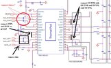
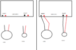
rjenkinsgb: Can you verify my last post, thats how i should connect the speakers ? Would you advice parallel or series connection of woofer and tweeter ? I need to know that to design the crossover.


audioguru: I am making multiple speakers, right now i am making a big one. I know how to calculate speaker enclosure so don't worry about that. I know i will need crossover, im working on it and someone is helping me. But first i need to know how to connect the speakers. I am using 25.6V 6S batteries and don't plan to switch to lower voltage anytime soon. As for distortion, we already talked about that. I will simply turn on the speaker, put on the loudest song, set mobile phone volume to 100%, increase the amplifiers volume knob until i hear distortion that is being annoying. And then i will glue the knob in place. I use mobile phones volume to control the speaker so if i ever have mobile phones volume at 100%, you better belive it that me or someone near me wants it to be as loud as possible and doesn't care about sound quality in the least. I have been trying to explain to you how i use my speaker. It is always used in a very loud place with a lot of people and alcohol involved. So after people have drank 6 beers, they just want to hear that silly disco or euro dance song from their youth as loud as possible. And belive me, no matter how strong the speaker is, even if its loud enough to wake the dead, there will always be someone that will say "i love that song, increase the volume !!". Now i understand that my usecase for the speaker is unique, what with most people here being sort of audiophiles or at least know what audio quality is. But this is not what this speaker is for. Sure i wan't it to sound as good as it can within my low budget, but loudness is number 1 priority and second is bass. Now when/if i make speakers for when im at home, listening to classical music, then i will go about it in a completely different way. But right now, im making a boombox.
As i mentioned, a very nice guy from this forum is helping me with the crossover since i never did anything beyond 1st order. He already made a nice crossover, i wont even pretend i understand it but he knows what hes doin since people loved his design. The bad news is that he made that crossover under the assumption that i will be using 2 mono channels and on each channel 1 speaker (on 1 channel woofer, on the other tweeter). But that is out of the question now since i am basicaly only getting 1 output. So if i connect the speakers to the same terminals, meaning in parallel, i suddenly have only 2 ohm impedance for which i have no freakin idea what is going to happen, if the amp is even ok with such low impedance. And if i connect the speakers in series, then again it needs a completely new crossover and probably brings tons of new problems. So i really need someone to clarify those important questions for me.


Do i connect in series or in parallel ? And why ?

Not that it makes any difference but to satisfy some curiosity, i am using the tweeter and woofer i bought for this project a long time ago and i have them at home. Woofer is SB Acoustics SB20PFC30-4 8", tweeter is Dayton Audio ND16FA-4 5/8". And i know i sound grumpy and i really am. Because i want this ready for my birthday party which is really not far away. So please, no more distortion and shrieking talk. Just say, put the red wire in the terminal (and i am quoting Al Bundy here so you know its serious ! :hilarious:)
Anyway, waiting for your replies so i can get to work. Let's go !! (Quoting A.B. again :joyful:)
 
Status
Not open for further replies.

Latest threads

New Articles From Microcontroller Tips

Back
Top