Continue to Site

Welcome to our site!

Electro Tech is an online community (with over 170,000 members) who enjoy talking about and building electronic circuits, projects and gadgets. To participate you need to register. Registration is free. Click here to register now.

  • Welcome to our site! Electro Tech is an online community (with over 170,000 members) who enjoy talking about and building electronic circuits, projects and gadgets. To participate you need to register. Registration is free. Click here to register now.

Stereo/Mic Mixer Stopped Working....

Status
Not open for further replies.

mech3d

New Member
I built a small stereo and mic mixer that used to work until I changed the output connector from mono to stereo so I didn't have to use an adapter on the cable to connect the mixer to the amplifier's aux. input.

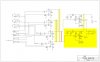
In the attached schematic what is highlighted in yellow are the parts I added and the line in red is what I took out.

I would really appreciated if any one could point me to my error. I am perplexed.


Thanks,
mech3d
 

Attachments

  • mixer_baseline_updated.jpg
    mixer_baseline_updated.jpg
    70.7 KB · Views: 696
I hope you haven't plugged a Mono plug into your stereo jack output because this would short out the left channel.
 
Hi RadioRon,

No, I was careful not to mix jack types. I am buzzing it out now but I still can't seem to find what I did wrong.
 
So, you took out the connection that is the red line and added the connections that are the two yellow highlighted lines on the left. I don't understand why you did this, because they do the same thing.

The only real change seems to be that you added the right channel amplifier on the right. I'm wondering why you didn't just short the left and right terminals on the stereo jack and drive both from the left channel amp. Anyways, perhaps the problem lies in that you have attached a second DC source to the junction in the middle and the DC bias is now upset and needs to be adjusted. A check of DC voltages on the various amps should give some clues.
 
Like RadioRon says, I don't think Q1-Q4 are getting enough operating voltage. Not really sure. I can't read the resistor values - they are too small to see clearly.
 
I think you both are right. I am making this more complicated than it has to be. All I wanted to do was replace the "main in" and "output" mono connectors (in my first schematic, not shown here) with stereo connectors and perhap duplicating the all that circuitry was not necessary. Simple shorting the left and right terminal jack would have been my solution.
 
Revised Mixer Schematic

Ok, I revised the schematic to what I think makes sense now. Notice that on the output I tied the left and right together to create a mono output.

What do think? Will it work?

Thanks,
mech3d
 

Attachments

  • mixer_rev3.jpg
    mixer_rev3.jpg
    68.4 KB · Views: 779
What is even more poor is my lack of experience with electronic curcuits. I found the schematic on the web and was trying to use it as a baseline for something to build off of.

I was attempting 3 inputs (2 mics and 1 stereo) and 1 output. I know, I should be using op-amps instead of transistors.
 
Ok, I revised the schematic to what I think makes sense now. Notice that on the output I tied the left and right together to create a mono output.

What do think? Will it work?

Thanks,
mech3d

It should work. All you are doing here is building-in the function that an external adapter used to give you. The only problem remains that you can't plug a mono connector into that stereo output, but you know that. And when you plug a stereo connector in, it won't matter if it is feeding a stereo load (which would place two high impedance inputs in parallel, which would be ok here), or a mono load.
 
If you put a resistor, say 1k, in series with each of pins 2 and 3 of the mono out jack (34) you should still have a useful output even if you accidentally put a mono plug into it.
 
Thanks for the tip. One question though, at what point then do I jumper 1 & 2 after or before the resistors?
 
Jumper 1 & 2 of what? Check the pin numbers of the output jack on your schematic and get back to me.....

You put the resistors on what your schematic shows as pins 2 & 3. Connect the loose ends together and hook that to the junction of R20 and C11.
 
Sorry for taking so long to get back to you.

I added the resistors per your instructions. How does this look now?

I built this on a bread board the other day (the earlier version without the 2 additional resistors) and it worked quite well. I will add these probably tonight.

I orginally put a jumper wire between pins 2 & 3 of the output because I wasn't sure how to get the 2 mono inputs to play on both the left and right outputs.

Ideally I would have preferred to keep the stereo out and have both mono inputs play on the left and right. But I couldn't figure out how to do that without duplicating the entire output section of the schematic. So I picked the next best thing, just combine everything and use the stereo output connector with a mono signal.

The reason I am using a stereo jack for the output in because the amplifier this connects to uses a left & right aux. input.

Anyway thanks again for all your help.
 

Attachments

  • mixer_baseline_rev4.jpg
    mixer_baseline_rev4.jpg
    84.5 KB · Views: 248
The output looks good to me. This way you can use the output with either a stereo or a mono plug.
 
Status
Not open for further replies.

Latest threads

New Articles From Microcontroller Tips

Back
Top