Follow along with the video below to see how to install our site as a web app on your home screen.
Note: This feature may not be available in some browsers.
flemmard said:HI,
I have attached my stepper motor wiring diagram.I have a doubt here.
White and black wires are grounded or connected to V+?
I also attached my datasheet.How do i test the motor?
THanks
ericgibbs said:hi,
Its a unipolar stepper motor, normally the centre taps of the windings [white/black] are connected to +12V supply.
The 4 driver transistors are connected to the other 4 wires and pull the 'ends' of the windings to 0V/common.
You have to 'drive' the transistors in the correct sequence in order to step the motor.
gramo said:Grab a multimeter and find the common/supply wires. Should be a couple hundred ohms between each winding and the common, heres what a unipolar stepper looks like;
**broken link removed**
From there, if your not sure what winding is connected to what wire, put a small length of tape on the shaft like a pointer
Then pick any winding wire, and connect power through it to the common, and then manually connect another. You will be able to see the step fairly easily with the tape attached to the shaft
**broken link removed**
ericgibbs said:hi,
Its a unipolar stepper motor, normally the centre taps of the windings [white/black] are connected to +12V supply.
The 4 driver transistors are connected to the other 4 wires and pull the 'ends' of the windings to 0V/common.
You have to 'drive' the transistors in the correct sequence in order to step the motor.
Hi, thanks for your reply.
Can you tell me which one is 1a,1b,2a,2b in my stepper motor wiring diagram?
I connected black and white to 12v directly and used other wires to connect to 5v for logic 1 and 0v for logic zero.
But it's not working
ericgibbs said:hi,
For testing which winding is which:
When the White and Black wires are connected to +12V, you connect the other wires, one at a time to 0V, the motor shaft should move one step, cw or ccw.
It shows you which are the respective end wires in YOUR diagram???
flemmard said:Hi gibbs,
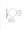
I have attached my stepper motor wiring configuration here.
I explain here what i did...
I connected Black, white to 12v [as you mentioned in your previous post]
then i connected Brown to logic 1 [5v] , rest of the wires to 0v...But it didn't move.
I tried different logic with the wires ....keeping black, white always to 12v.But in vain.![]()
any suggestion?