Electro Tech is an online community (with over 170,000 members) who enjoy talking about and building electronic circuits, projects and gadgets. To participate you need to register. Registration is free. Click here to register now.
Welcome to our site! Electro Tech is an online community (with over 170,000 members) who enjoy talking about and building electronic circuits, projects and gadgets. To participate you need to register. Registration is free. Click here to register now.
HI,
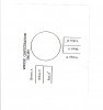
I have attached my stepper motor wiring diagram.I have a doubt here.
White and black wires are grounded or connected to V+?
I also attached my datasheet.How do i test the motor?
THanks
HI,
I have attached my stepper motor wiring diagram.I have a doubt here.
White and black wires are grounded or connected to V+?
I also attached my datasheet.How do i test the motor?
THanks
Grab a multimeter and find the common/supply wires. Should be a couple hundred ohms between each winding and the common, heres what a unipolar stepper looks like; **broken link removed**
From there, if your not sure what winding is connected to what wire, put a small length of tape on the shaft like a pointer
Then pick any winding wire, and connect power through it to the common, and then manually connect another. You will be able to see the step fairly easily with the tape attached to the shaft
Hi, thanks for your reply.
Can you tell me which one is 1a,1b,2a,2b in my stepper motor wiring diagram?
I connected black and white[ a and b as in your convention] to 12v directly and used other wires to connect to 5v for logic 1 and 0v for logic zero.
But it's not working
For testing which winding is which:
When the White and Black wires are connected to +12V, you connect the other wires, one at a time to 0V, the motor shaft should move one step, cw or ccw.
It shows you which are the respective end wires in YOUR diagram???
For testing which winding is which:
When the White and Black wires are connected to +12V, you connect the other wires, one at a time to 0V, the motor shaft should move one step, cw or ccw.
It shows you which are the respective end wires in YOUR diagram???
Hi gibbs,
I have attached my stepper motor wiring configuration here.
I explain here what i did...
I connected Black, white to 12v [as you mentioned in your previous post]
then i connected Brown to logic 1 [5v] , rest of the wires to 0v...But it didn't move.
I tried different logic with the wires ....keeping black, white always to 12v.But in vain.
any suggestion?
This site uses cookies to help personalise content, tailor your experience and to keep you logged in if you register.
By continuing to use this site, you are consenting to our use of cookies.