Electro Tech is an online community (with over 170,000 members) who enjoy talking about and building electronic circuits, projects and gadgets. To participate you need to register. Registration is free. Click here to register now.
Welcome to our site! Electro Tech is an online community (with over 170,000 members) who enjoy talking about and building electronic circuits, projects and gadgets. To participate you need to register. Registration is free. Click here to register now.
You been in my toolbox again !
That's not my soldering iron though, that's my colonic pile popper .. .. you need to put that back where I'd like to put it !!
I think the original schematic is flawed in several ways.
1) TL084 & BC557 transistor selection and slew rate problems resulting in a partial sine instead of a pulse. Slew rate is reduced such that the pulse is 22% of a sine instead of 50% of a square wave.
It should be a current source pulse such that output voltage is proportional to ESR.
Try reducing 100kHZ towards 10kHz with a larger cap. for C3 1nF-> 10nF then recapture waveforms until a better driver is found. It would be slightly better to bypass the transistor all together and drive the TL084 direct to bridge. with +4V to 0.5K load for 8mA using a bipolar signal around Virt. Gnd rather than a unipolar pulse with DC above Virtual ground.
We have a cap manufacturer on the board :O, I got a dislike on my post ROFLMAO. My LCR meter gives you a choice of frequency and the results can be different from the same cap depending on frequency, but so far all the sheets I have looked at say 100kH with a couple using 10kH.
But like you say if they are out its normally way off not just a little bit.
Based on other circuits found while surfing, the intent might be for an intentionally slew-rate limited or R-C risetime limited square wave to approximate a sine wave. Not a great approximation for sure, but better than nuttin. Still, I vote for adding a true sine wave oscillator section. A phase-shift osc would have way lower high freq harmonics and good-enough amplitude stability without all of that Wein-ing.
Oooh... another chance for me to plug one of my favourate circuits?
Perhaps the circuit I use here would be of use - a two transistor phase-shift oscillator with Wien-bridge style amplitude control. It gives THD around 1% is seem to remember.
Thank you very much for your suggested circuit as an alternative method I could use to lose the will to live !
I feel certain that if I ever were to need a circuit to oscillate my navel, this would be the one I would chose, for sure. I marvel at the notion that such a circuit would have the power to efficiently move the bulk that surrounds my navel sufficiently to cause an oscillation and feel sure if it were achieved it would be a sore wave for sure .. .. ..
Oooh... another chance for me to plug one of my favourate circuits?
Perhaps the circuit I use here would be of use - a two transistor phase-shift oscillator with Wien-bridge style amplitude control. It gives THD around 1% is seem to remember.
I've been reading through your ESR meter posted detail .. .. can't see any problem, as you say, much more straightforward.
Are you aware there has been a revised version published in 2004 ? Some variations ... .. some of the obsolete components have been upgraded; only one battery used;
Basically, looks the same to me .. .. any comments ?
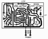
Firstly, thank you for going to the trouble of producing this PCB .. .. ..
Unfortunately, at this moment in time I don't have the means to produce a custom PCB .. I tried etching once .. .. never, ever again .. I got into such a mess .. .. ... I have a small CNC machine planned and partly manufactured for the purpose, but I'm a way off completion . I have the x axis bed complete and I'm currently working on the gantry, but there's a lot of work to do yet.
Maybe some of the other members will be in a position to make use of your plan immediately .. but I will keep it in store to try out my machine in the future.
This site uses cookies to help personalise content, tailor your experience and to keep you logged in if you register.
By continuing to use this site, you are consenting to our use of cookies.