Electro Tech is an online community (with over 170,000 members) who enjoy talking about and building electronic circuits, projects and gadgets. To participate you need to register. Registration is free. Click here to register now.
Welcome to our site! Electro Tech is an online community (with over 170,000 members) who enjoy talking about and building electronic circuits, projects and gadgets. To participate you need to register. Registration is free. Click here to register now.
Load LTSpice and give it a try. You won't learn much if you have someone else do it. We're not here to do your work but, if you have problems, we're here to help.
Load LTSpice and give it a try. You won't learn much if you have someone else do it. We're not here to do your work but, if you have problems, we're here to help.
Ok, spice is fun and very helpful, but how do I pick an op amp that represents LM324, TLC27M9CN, amplifier, comparator or a FET that represents IRF3025? Is there a table, is it in the down loadable library?
Thanks,
Kinarfi
Can someone please help with Spice, I'm trying simulate a 110 amp N channel mos FET IRF3205, but I don't know what to do with length, width, areas, or perimeters, or if I want NMOS or NMOS4.
Please, some advice!
Kinarfi
Thanks MrAl, I'll try to enter this, but may have to ask How
After plugging in the first diagram, I moved on to this and it works,
Good tool, this spice!
Thanks again,
Kinarfi
Here is a running LTSpice sim incorporating the IRF3205 model posted above. I included a zip file, which should run if you unpack it into a new directory.
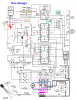
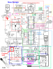
Thanks Mike, sorry for the slow come back, had guests and was downstairs trying to make my new circuit work and play with mechanical toys, thanks for suggesting spice. Learning, but it helped me simplify the circuit after you suggested that there were other ways to accomplish what I was trying to do, got rid of a bunch of pots. Take a look at the new design, a lot simpler than before, but if you can tell me, why won't my scr shut off when the drive to FETS 2 & 3 are shut down?
Thanks,
Jeff
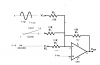
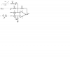
I need some help, Please. Originally, as the relay started to activate, the voltage that activated C4 would go to 0 and C4 never gets closed and couldn't seal itself in, So I put an SCR in the circuit to hold power for C4 to close and seal itself in via FETs 2 or 3. When FETs 2 or 3 turn off, the SCR should turn off also, but it doesn't.
I always called this a relay race, and the important one is losing the race.
In this circuit, the pulsed 9.8 volts come from an op-amp that is triggered by a voltage rise on a .1 ohm resistor, the SCR fires but, still won't turn off when FETs 2 or 3 turn off.
Anyone have any ideas or alternate ways to defeat the relay race?
The gate voltage on the SCR should be a 0 because the diode is dropping the voltage offset of the op-amp.
I've also learned not the ask thing like how do you make a 'model' for an SCR in spice, so I am asking where do I go to learn how to. I have the .sub file. and I found out you can only have one include in a design. Again, where are the instructions, manual, how to's for Spice,
In other words, you don't have to give a fish to eat, or even teach me how to fish, just tell me where to go to learn, please and
Thanks
Kinarfi
First off, that diode on the FET gate is either drawn wrong or is not connected
properly. It should be reversed. It may already be that way in the circuit if
the FET is really turning on, or maybe the FET is shorted anode to cathode
so it looks like it is turning on but it isnt, it's always on.
Can you draw a diagram to show exactly what contacts close when C4 is energized?
It's a little difficult to tell from that drawing. Show contacts as shorted with
a red line or something when the coil is not energized, then with a blue line
which contacts are closed when the coil is energized.
Thanks, and no, have not joined but will, and yep, I get a lot more water that way, hopeful, I can even take a bath, and in private, too.
MrAl, the diode was drawn backwards, The SCR turns on like it should, but won't turn off
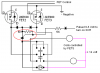
I've posted this earlier, but, what I'm doing is controlling a motor via a stain gauge and the relay is to remove the signal to the FET that is controlling another relay that is connecting the motor to a PWM signal and + power. When the motor reaches the end of it's travel, the motor stalls and current rises and the voltage across the .1 ohm goes up and is compared to a set voltage and fire the SCR which stays fired to pull the relay in. The normally closed and open contact are indicated by the drawing in the middle of the relay.
This site uses cookies to help personalise content, tailor your experience and to keep you logged in if you register.
By continuing to use this site, you are consenting to our use of cookies.

")