Continue to Site

Welcome to our site!

Electro Tech is an online community (with over 170,000 members) who enjoy talking about and building electronic circuits, projects and gadgets. To participate you need to register. Registration is free. Click here to register now.

  • Welcome to our site! Electro Tech is an online community (with over 170,000 members) who enjoy talking about and building electronic circuits, projects and gadgets. To participate you need to register. Registration is free. Click here to register now.

Spice

Status
Not open for further replies.
Hi,


So it's a double pole double throw relay then?
 
Hi,


So it's a double pole double throw relay then?

Yes sir, one side controls C2 and the other C3 and when the over current Opamp fires at end of travel, SCR fires, C4 activate and It drops out C2 or C3, (Both) and the power that was going to C2 or C3 now goes to C4 until the Strain gauge is relaxed, then Fets 2 &3 shut down and SCR is supposed to Shut down.
 
Hi,

Ok, it may be simply leakage then, assuming the scheme works as is anyway.

Did you try a resistor, like 1k from the cathode of the SCR to +12v (+Battery) ?
 
Last edited:
Not yet, take a look at this drawing, I have 10 v regulated and 5 volt reference and yes everything is work quite well except for the SCR shutting down.
 

Attachments

  • post.PNG
    post.PNG
    17.5 KB · Views: 130
Last edited:
Here is the correct connection...
(goes to other side of coil C4)

Oh hey you dont have any inductive kickback diodes installed?
 

Attachments

  • NEW-1.gif
    NEW-1.gif
    10.3 KB · Views: 145
Last edited:
Where? on the coils?
 
Where? on the coils?


Hi,

Yes. They have quite a high voltage kickback when they turn off
unless there is some way to prevent that.
 
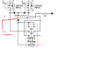
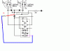
Got things straightened out, I think there may have been an invisible solder bridge firing the SCR, it now turns off with FETs 2 & 3, however, it turns right back on when relays close, too many spikes in the system.
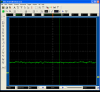
I was watching the current on a .1 ohm resistor and when a motor is driven by a square wave, the amperage during the on time is higher than when the power is 100%.
Any way, this has been a very educational project, but I don't think it will work for my purposes.
Now on to my next idea.
Kinarfi
Thanks to all those who chimed in to help. I appreciate it very much.
 

Attachments

  • zz.png
    zz.png
    30.3 KB · Views: 140
  • xx.png
    xx.png
    29.6 KB · Views: 165
Status
Not open for further replies.

Latest threads

New Articles From Microcontroller Tips

Back
Top