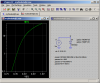
When I was playing I had trouble getting this curve and the Vf curve at the same time. I'm just curious if yours gets both pretty close as it is a parameter that could effect performance.
Edit:
Cut the bottom off the picture. The x is % of reverse voltage.
Hello again,
After reading eTech's most recent post i see what one of your problems is. You are trying to use the exact same exponential for the negative voltage characteristic as for the positive (forward) voltage characteristic.
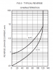
A different exponential is used for the negative part of the response, if you choose to even do that. 'Is' is the 'leakage current' in the reverse mode, so to approximate you can think of it as a small current (leakage) until it hits the breakdown voltage, and then it dives very low (very high amplitude negative current).
So you have to switch equations when you go with voltages less than 0 (negative voltages), or just assume the leakage current until breakdown when the voltage goes negative. Since you probably wont need the breakdown characteristic, you can probably just use -Is as the current in the reverse mode. If you really think you need the curve then we'll have to look that up, but it will be a slightly different exponential which i think includes the BV parameter (which would make sense).
I should add that the new exponential does not kick in right away, but somewhere near the BV i think. Otherwise it is Is.
Also, some spice representations will not really take advantage of this depiction of the reverse characteristic, but will actually use a very small 'Is' and model the reverse leakage with a parallel resistor Rp instead. This value may be very high too, like 1G Ohms, or lower like 10M Ohms. For the 1N4148 diode for example it would be very high like 1G Ohms. For this kind of depiction, the leakage current parameter would be made very low like 2 picoamps, so it does not contribute much to the actual reverse response, so the parallel resistor then takes on the responsibility of modeling the reverse leakage. In cases where there is no Rp specified (with or without a very tiny 'Is"), the parallel resistance would be 1/GMIN for example, where GMIN is a global parameter that affects many component parameters as default.
Also, "Is" itself does not really kick in at exactly 0.000000 volts, but waits until the voltage gets a little bit negative, possibly around -0.25v. I think the value is taken as -5*N*Vt.