EvilGenius
Member
Hello
For a while I have been trying to find a pre-made board that is able to convert SPI signal (not DMX) to RGB to drive high power RGB Pixels (10W), to no avail. I had a previous post regarding this and gave up since I could not find such a board and it was cost prohibitive to manufacture. I originally gave in using WS2811 Pixel Board combined with an RGB amplifier. It was all good with the exception that I had no control over the LED currents and the pixel could easily overheat and self-destruct even with series resistors. Worth mentioning WS2811 is a 3-channel (18.5ma constant current) pixel driver that can receive SPI signal, buffers what it needs and pass on the remaining signal to the next pixel with no additional external clock. The buffer triggers 3 outputs to generate the color on the RGB pixel. This is done by a start bit, then sequence of 8bit for R, 8bit for G, 8bit for B, then a stop bit and auto latch. Its outputs can only "sink" (active low) maximum of 18.5ma per channel.
Operational Goal: Building a device that can receive SPI signal from microcontroller, or Programmable SD-RAM SPI Controller, or SPI signal from a DMX to SPI controller which utilizes DMX signal from a controller, or a PC program such as Light-O-Rama via a dongle. Device to have 3-Wires in/out (Data, +12, Gnd) for daisy chaining.
Searching on the net I came across a simple dual NPN CCR which peaked my interest yet it was not exactly what I needed since it required Positive trigger (Active High) to operate it. I reconfigured the design to use PNP transistors for Active low outputs of WS2811.
Objective: Build a device that is able to convert SPI to RGB
1- Be very low cost
2- Be very small (to fit an HP RGB metal case)
3- Be able to sink 300mA per channel (with flexibility to go a bit higher or lower by selecting Rs and Rx)
4- Use fairly common parts that are easy to find and inexpensive
5- Operate with minimum I/O wires (Single data line in/out)
6- Provide for constant current for each channel
7- Be able to drive 10W high power RGB module that runs on 12VDC
Parameters:
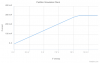
I-LED=300mA (under utilized vs. 350mA max)
Ideal Transistors: PNP To-92 Case, no heat-sink, Power Diss. = 625mW, hfe= about40, Ic=600mA, Vbe(on)=0.65, If Vbe(on) is not available Vbe(sat)=0.75 (example: 2N4403). Setting aside the board cost (board can be build dirt cheap at home and parts are thru-hole), the part cost is under $1 USD.
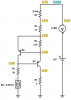
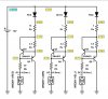
Here is the circuit simulated schematics and PCB layout (1.15x1.25 inches, 0.25 height)
For a while I have been trying to find a pre-made board that is able to convert SPI signal (not DMX) to RGB to drive high power RGB Pixels (10W), to no avail. I had a previous post regarding this and gave up since I could not find such a board and it was cost prohibitive to manufacture. I originally gave in using WS2811 Pixel Board combined with an RGB amplifier. It was all good with the exception that I had no control over the LED currents and the pixel could easily overheat and self-destruct even with series resistors. Worth mentioning WS2811 is a 3-channel (18.5ma constant current) pixel driver that can receive SPI signal, buffers what it needs and pass on the remaining signal to the next pixel with no additional external clock. The buffer triggers 3 outputs to generate the color on the RGB pixel. This is done by a start bit, then sequence of 8bit for R, 8bit for G, 8bit for B, then a stop bit and auto latch. Its outputs can only "sink" (active low) maximum of 18.5ma per channel.
Operational Goal: Building a device that can receive SPI signal from microcontroller, or Programmable SD-RAM SPI Controller, or SPI signal from a DMX to SPI controller which utilizes DMX signal from a controller, or a PC program such as Light-O-Rama via a dongle. Device to have 3-Wires in/out (Data, +12, Gnd) for daisy chaining.
Searching on the net I came across a simple dual NPN CCR which peaked my interest yet it was not exactly what I needed since it required Positive trigger (Active High) to operate it. I reconfigured the design to use PNP transistors for Active low outputs of WS2811.
Objective: Build a device that is able to convert SPI to RGB
1- Be very low cost
2- Be very small (to fit an HP RGB metal case)
3- Be able to sink 300mA per channel (with flexibility to go a bit higher or lower by selecting Rs and Rx)
4- Use fairly common parts that are easy to find and inexpensive
5- Operate with minimum I/O wires (Single data line in/out)
6- Provide for constant current for each channel
7- Be able to drive 10W high power RGB module that runs on 12VDC
Parameters:
I-LED=300mA (under utilized vs. 350mA max)
Ideal Transistors: PNP To-92 Case, no heat-sink, Power Diss. = 625mW, hfe= about40, Ic=600mA, Vbe(on)=0.65, If Vbe(on) is not available Vbe(sat)=0.75 (example: 2N4403). Setting aside the board cost (board can be build dirt cheap at home and parts are thru-hole), the part cost is under $1 USD.
Here is the circuit simulated schematics and PCB layout (1.15x1.25 inches, 0.25 height)
Attachments
Last edited: