Electro Tech is an online community (with over 170,000 members) who enjoy talking about and building electronic circuits, projects and gadgets. To participate you need to register. Registration is free. Click here to register now.
Welcome to our site! Electro Tech is an online community (with over 170,000 members) who enjoy talking about and building electronic circuits, projects and gadgets. To participate you need to register. Registration is free. Click here to register now.
I'm not much of an electronics expert, but I would guess you would make those voltage dividers pull up by making the high side resistor a bit weaker than the low side one?
But don't quote me on that. Now someone will give you a better answer and I'll learn something.
Chances are it'll work fine without pullups on the lines you're using, but I don't know for sure.
I am not sure what that means, I don't see how those 3 resistors would allow give a high 3v when there is a 0volt output on the 5v line and then drop low when the 5 volts output is high.
Warning, i am very slow at picking up electronics theory....
Thanks Bill, not really sure I understand your "tristate" statement - perhaps I really should get my hands on a 74XX245 as most of the examples suggest (which has pullups on the 3v bus side which is confusing).
Just correct me if I am wrong but would the difference between a circuit which uses pullups and a circuit that does'nt mean that i should alter the CKE CKP appropiately (active high vs active low)?
The pins are driven from both the master and slave in 3 wire SPI mode.
Since your microcontroller is the master clock its SDO and SCK pins are 0-5V drivers and the SD cards SDO is driven not open collector.
The only real problem will be if your micro has Schmidt trigger inputs on SDI as 3.3V will probably be too low for that input.
A neat chip is the 74VC1T45 for level translation, or a 74HCT125 or a MOSFET may work.
Then it's going to need a boost on the SDI pin. The 74HCT125 is common and it works for SPI. The resistor bits are fine for the SDK, SDO and CE outputs from the PIC.
UTMonkey, may I ask what resources you are using in your project? I too want to interface an SD card and a PIC, but have only been reading the application notes.
just a 18f2550 on a breadboard using (or attempting to use) hardware SPI to an SDCard (powered by 3.3v) via resistors forming a potential divider to convert 5v outputs to 3v.
There are loads of resources and threads on this site which are really useful.
The problem I am having is at the reset stage of the SD card (the very beginning), the SPI module does report receiving data but it is either 0xC0 or 0xE0 when it should be 0x01.
I am trying to rule out whether the potential dividers are at fault or perhaps is should take the more robust approach and use level shifters (74x125, 74x245).
Then it's going to need a boost on the SDI pin. The 74HCT125 is common and it works for SPI. The resistor bits are fine for the SDK, SDO and CE outputs from the PIC.
Well you will need a level shifter when using the SPI in hardware for the SDI pin. 3.3V is just not high enough for the Schmitt inputs on a 5V PIC. I'd have to check the datasheet but I recall it's something like VCC-0.8 (4.2V) is a 1.
I'm trying to get this to work as well. I'm using a 3.3v chip, though, so level translators aren't my issue, but I thought I'd keep this all in one thread.
I have tried a microsd card and a few regular sd cards. On the microsd card setup, I have nothing pulled up. On the SD card setup I have the unused data lines pulled up.
I'm getting no response from the card at all. I've tried quite a few variations with changing the way I'm working the protocol, and delays and such, but still nothing from any of the cards.
Here's my logic output for the initialization. I send 10 0xFF's to get the initialization clocks over with, then I send the CMD0. 0x40,0x00,0x00,0x00,0x00,0x95. I check 20 times for a response before resending this initialization, and continue to get the same no response.
Logic view:
**broken link removed**
I'm hoping someone can see something that I can't otherwise I'm just going to have to keep experimenting.
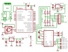
Setup:
**broken link removed**
EDIT: Actually, I just checked my setup again, and only the unused pins on the SD card breakout are being pulled up. Pin 9 and 8. Otherwise the datalines are direct connect. Edited text above.
This site uses cookies to help personalise content, tailor your experience and to keep you logged in if you register.
By continuing to use this site, you are consenting to our use of cookies.