The PDF for MAX662A lists:
https://www.electro-tech-online.com/custompdfs/2009/05/MAX662A.pdf
The capacitance values of the charge-pump capacitors C1 and C2 are critical. Use ceramic or tantalum capacitors in the 0.22μF to 1.0μF range. For applications requiring operation over extended and/or military temperature
ranges, use 1.0μF tantalum capacitors for C1 and C2
So the diagram should have a plus sign for the shown capacitors? I mean I need polarized capacitors?
I have chosen these for C1, C2:
KEMET|T110A105K035AT|CAPACITOR, AXIAL, CASE A, 1UF | Farnell LT
Also I found:
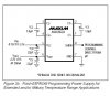
The values of C4 and C5 can be reduced to 2μF and 1μF, respectively, when using ceramic capacitors. If using aluminum electrolytics, choose capacitance values of 10μF or larger for C4 and C5.
See figure 3b in the PDF it has the plus signs back? Also they use 22uf caps there.
So I'm confused, can anyone list best correct capacitors for my project from these 2 sites:
www.farnell.com www.elfalektronika.lt (choose language english).
https://www.electro-tech-online.com/custompdfs/2009/05/MAX662A.pdf
The capacitance values of the charge-pump capacitors C1 and C2 are critical. Use ceramic or tantalum capacitors in the 0.22μF to 1.0μF range. For applications requiring operation over extended and/or military temperature
ranges, use 1.0μF tantalum capacitors for C1 and C2
So the diagram should have a plus sign for the shown capacitors? I mean I need polarized capacitors?
I have chosen these for C1, C2:
KEMET|T110A105K035AT|CAPACITOR, AXIAL, CASE A, 1UF | Farnell LT
Also I found:
The values of C4 and C5 can be reduced to 2μF and 1μF, respectively, when using ceramic capacitors. If using aluminum electrolytics, choose capacitance values of 10μF or larger for C4 and C5.
See figure 3b in the PDF it has the plus signs back? Also they use 22uf caps there.
So I'm confused, can anyone list best correct capacitors for my project from these 2 sites:
www.farnell.com www.elfalektronika.lt (choose language english).
Last edited:

")

