Continue to Site

Welcome to our site!

Electro Tech is an online community (with over 170,000 members) who enjoy talking about and building electronic circuits, projects and gadgets. To participate you need to register. Registration is free. Click here to register now.

  • Welcome to our site! Electro Tech is an online community (with over 170,000 members) who enjoy talking about and building electronic circuits, projects and gadgets. To participate you need to register. Registration is free. Click here to register now.

Spectrophotometry very stable current light source circuit

Status
Not open for further replies.
But why then they are called The LM134/LM234/LM334 are 3-terminal adjustable current sources, not voltage sources?

Also what is difference between 134 / 234 /334?

Woops!
I thought you were still looking at the CV ic's...:eek:

It sounds an interesting project.
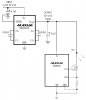
 
I seems I got 2 solutions proposed here (thanks BTW):

1st LM234/334 IC
2nd MAX6126 IC

Just checked my local store, I can order:

MAX6126AASA25+ Voltage References Series 2.5V out 5 V
MAX6126BASA21 V-ref NSO Voltage References Series 2.048V out 5 V
MAX6126BASA25 V-ref NSO Voltage References Series 2.5V out 2.5V
MAX6126BASA30 V-ref NSO
MAX6126BASA41 V-ref NSO
MAX6126BASA50 V-ref NSO

LM334Z
LM334M/NOPB.
LM334Z/NOPB.
LM334H
LM334S8#PBF
LM334M/NOPB
LM334Z/NOPB
LM334SM/NOPB
LM334H.
LM334Z.
LM334SM
LM334M
LM334Z


LM234Z-3/NOPB.
LM234DT
LM234Z.
LM234DT
LM234Z-3/NOPB
LM234Z-3
LM234Z

it seems I can't get 134 at all :(
What model do I need? Would USB be OK for providing 5V, what about pulsed interference?

I'm also waiting for someone to propose a schematic for MAX6126 chip (what tranzistor and rezistor I need for 8mA) as it has got "Low 200mV (max) Dropout Voltage" versus 1V for LM234/334 chip.
The tranzistor and rezistor for MAX chip will eat some voltage too so perhaps 200mV is not real here and could be higher.
 
Last edited:
The LM134/234/334 is nice, but what about accuracy and thermal stability? I did not fully understand that part of PDF. Remember I nedd to reach stability at the second number after the decimal point or better.


Did you mean this schematic? The datasheet contains many packages and type of this chip which one would I need?

It shows one transistor and one resistor connected. Could you help me choose these components too? I have no knowledge how to do it myself.

I apologize if my question seems stupid or something and the answer seem obvious.
My simulator microcap9 does not have this part so I can't check anything.

Yes, that's the schematic, but I realize now that it won't work with only a 5 volt supply. Even if you use the device having a 2 volt output, you need a supply voltage of at least 6 volts, preferably greater. Your LED has a 3.9 volt forward voltage drop. (2+3.9=5.9v)
 
This will get past the 5V problem. Now's it's a matter of finding the right MOSFET. Next time.
 

Attachments

  • LED.jpg
    LED.jpg
    54.1 KB · Views: 364
The MAX6126 is a nice bug. It's probably not significant, but it would be good if the datasheet spec'd the bias current requirements (and temp variation) on the OUTS pin. Maybe I missed it.
 
The MAX6126 is a nice bug. It's probably not significant, but it would be good if the datasheet spec'd the bias current requirements (and temp variation) on the OUTS pin. Maybe I missed it.

I did see the tempco on the output (in the low PPMs). I wonder how great the voltage difference allowable is between the voltage at the sense input and the output voltage. I didn't see that, and for the current source it's important unless a bjt is used (in which case the voltage difference is not that much).
 
Thanks for the schematic. I really appreciate your work. It would be nice if it would work from 5V as using USB is convenient (every laptop has one).

What is bias?

Perhaps using MAX662A (that makes 12V) and (LM234/334) would work if MAX6126 has a problem with bias?

But if it's not possible then, I guess I have to buy 12V wall adapter for it but I want to this only as a last resort.
 
Smilem, I came up with the parts on the attached. Mind you, have I have not used any of these particular Maxim parts in my experience. Based on the datasheets, I think it is a workable solution.
 

Attachments

  • LED.jpg
    LED.jpg
    63.3 KB · Views: 242
this is a precision current source. the accuracy is dependent on the tolerances of the resistors and your voltage reference. the feedback loop excercises extremely tight control of the current by sensing the voltage across the load. R13 is the scaling resistor. the National Semiconductor App Note makes interesting reading and is available here:
**broken link removed**


i've actually built a working model of this current source, and it's an excellent circuit. i built a high power version of it because i needed a 1Arms AC current source (i replaced the DC voltage reference with an oscillator) for an accurate impedance meter. if you're using it to control an LED, any good op amp will do.
 

Attachments

  • howlandimproved.jpg
    howlandimproved.jpg
    19.8 KB · Views: 482
Last edited:
Smilem, I came up with the parts on the attached. Mind you, have I have not used any of these particular Maxim parts in my experience. Based on the datasheets, I think it is a workable solution.

Thanks for the circuit.

I cant' get MAX6126AASA50 :( , instead I can get MAX6126BASA50 (±0.06%; 5ppm/°C; 5.2 ~ 12.6V; 10mA; 380µA) or ADR425BRZ (±0.04%; 3ppm/°C; 7 ~ 18V; 10mA; 500µA;). Do you think it will be ok to use MAX6126BASA50?
 
Last edited:
Thanks for the circuit.

I cant' get MAX6126AASA50 :( , instead I can get MAX6126BASA50 (±0.06%; 5ppm/°C; 5.2 ~ 12.6V; 10mA; 380µA) or ADR425BRZ (±0.04%; 3ppm/°C; 7 ~ 18V; 10mA; 500µA;). Do you think it will be ok to use MAX6126BASA50?

Yes, that variant is fine. You are more interested in stability over time and temperature than the actual current level at turn-on. The initial current value is adjusted by tweaking the 330 ohm resistor, anyway, in this circuit.
 
Thanks. I'll order the parts then :)

I'm still woried that they are SMD, I will harve hard time soldering them.
I plan to use this rezistor
• Res MF 330ohm 0,1% 15ppm (282-3) Uni-Ohm 0.6W
 
Last edited:
I'm still woried that they are SMD, I will harve hard time soldering them.
I plan to use this rezistor
• Res MF 330ohm 0,1% 15ppm (282-3) Uni-Ohm 0.6W

Yeah, it's not as easy to home-brew as it was. Get the magnifier out. :D I would use "dead bug" construction on a piece of copper clad PCB material. My favorite method, though not the prettiest.

That resistor is a good, stable one. Best wishes.
 
Do I need to put 662A and 6126 IC so that it has thermal contact with some sort heat spreader like glue it like "dead bug" to a small piece of copper PCB using thermal glue then use it as normal component?

Also I need MAX662ACPA or MAX662ACPA+ (this is 3 times more expensive for some reason), PDF is the same.
Should I choose some high accuracy capacitors too, temperature stable? Unfortunately I don't know how to distinguish them, or it does not matter?
 
Last edited:
The thermal stability of the part is better than the 330 resistor and the part will hardly self-heat much. I use electronics grade, silicon RTV (not the vinegar smelling type), which happens to have good thermal conductivity. The capacitors don't need to be precision values, just good quality ceramic or tantalum.

I don't know the what the + means at the end of the 662 part number. The one without the plus will work fine.
 
High-K ceramics are temperature unstable (X7R, Y5V, etc). C0G/NP0 type ceramics should be very temperature stable.

As for the tantalums, I have no idea. I do know they are preferred in sub-zero conditions due to having a solid electrolyte vs. your standard aluminum electrolytic.
 
The temperature stability of the capacitors is not an issue with regards to the stability of the current through the LED in the circuit. The capacitors are used only to reduce ripple current, provide charge storage, reduce noise, or filter spikes. Any temperature instability in the capacitor at the gate of the FET is countered by the error amplifier inside MAX precision source, if that instability has any effect at all. Any temperature instability in the other caps is irrelevant.

Actually, there are ceramic caps with very good temperature stability. They are known as NP0 types.
 
Last edited:
If they are just power supply filter caps like ccurtis said, then you don't need C0G/NP0. X7R and X5R will be fine in that case. So will aluminum electrolytics.
 
Last edited:
Status
Not open for further replies.

Latest threads

Back
Top