Continue to Site

Welcome to our site!

Electro Tech is an online community (with over 170,000 members) who enjoy talking about and building electronic circuits, projects and gadgets. To participate you need to register. Registration is free. Click here to register now.

  • Welcome to our site! Electro Tech is an online community (with over 170,000 members) who enjoy talking about and building electronic circuits, projects and gadgets. To participate you need to register. Registration is free. Click here to register now.

Specific Counter on Breadboard

Status
Not open for further replies.

Renick Marsh

New Member
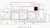
I would really appreciate some help with the following...I'm trying to wire a counter on a breadboard that counts in a specific sequence ( 2,6,7,5,1,8,0 ). I figured out the Logic Form and the JK Logic Programming part, but still fuzzy on K-Maps and how to wire the logic gates. If someone could help me with the wiring schematic, I would be very grateful. Thank You.

I'm working with the following...

555 Timer ( Working )
Man72 Seven Segment Display wired to a 7447 ( Counts 0,1 )
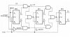
2 JK Flip Flop Chips ( 4 JK Flip Flops Total )
1 Quad AND Gate Chip ( Can use others if need be )
1 Quad OR Gate Chip ( Can use others if need be )
Multisim v. 13

Thanks again,

Renick Marsh
 
What issues do you have with K-maps? If you've know the logic you need to make this work then the wiring up should be simple enough.

Personally I would use a decade counter with the 7th output connected to reset and outputs 1-7 connected to the relevant 7447 inputs through a series diode and 10k pull down resistor.
For example:
on count 1, output 1 of the 4017 is high, this is connected to input B (via series diode) of the 7447 giving a '2'
on count 2, output 2 of the 4017 is high, this is connected to input C & B (via series diode) of the 7447 giving a '6'
....
on count 7, output 7 of the 4017 is high, this is connected to reset of the 4017 and thus all 7447 inputs are low giving a '0'
The pattern then repeats.


Or do you have to use logic gates and flip flops for some reason?
 
Thanks for the reply.

I've found a 7490 chip in my toolbox...will that work??? Also, I've already made a 0-9 decade counter using logic gates and flip flops, but I had a wiring schematic to follow. Could that be altered to count specific numbers? I can upload the schematic if need be. Trying to figure this out without a schematic is confusing. Thanks again for the help.
 
You could use a 7490 but it wouldn't work in the way I described above, it would need additional logic.
Your 0-9 decade counter should work fine if connected up in the way i described above.
Please do upload a schematic, I'd do one myself but i'm really busy until next week so wont have time I'm afraid.
 
I've included schematics of two counters I have already completed and the work I've done so far on the specific counter...Not sure were to go from here. Thanks again :)
 

Attachments

  • Up Down Counter(0-7).jpg
    Up Down Counter(0-7).jpg
    170.8 KB · Views: 345
  • Specific Counter.txt
    779 bytes · Views: 145
  • Decade Counter(0-9).jpg
    Decade Counter(0-9).jpg
    180.8 KB · Views: 361
With a little help from my Instructor, I finally figured out the K-Maps and Boolean Expressions. From there I was all good. It took 4 JK Flip Flops and 6 AND gates. I've included a schematic of the drawing I did in Multisim. Thanks again.
 

Attachments

  • Specific Counter.jpg
    Specific Counter.jpg
    218.8 KB · Views: 246
Status
Not open for further replies.

Latest threads

New Articles From Microcontroller Tips

Back
Top