Continue to Site

Welcome to our site!

Electro Tech is an online community (with over 170,000 members) who enjoy talking about and building electronic circuits, projects and gadgets. To participate you need to register. Registration is free. Click here to register now.

  • Welcome to our site! Electro Tech is an online community (with over 170,000 members) who enjoy talking about and building electronic circuits, projects and gadgets. To participate you need to register. Registration is free. Click here to register now.

Some questions about RF choke.

Status
Not open for further replies.

hanhan

Member
Hi, please help me with this section from my text book about power amplifier.
power-amplifier-1-modified-jpg.75114

power-amplifier-2-jpg.75115

power-amplifier-3-jpg.75116


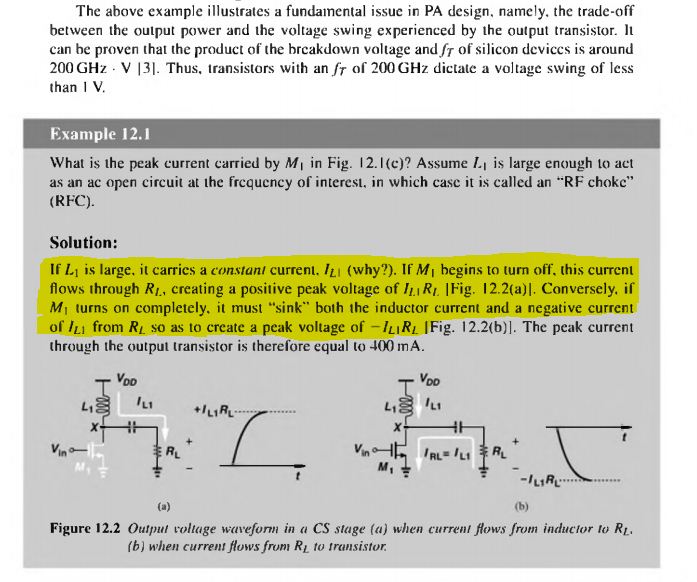
Q1: If L1 is large, it carries a constant current IL1 (why?)
My answer: I think Vin includes two components: DC bias and ac signal. Therefore, the current flows the inductor also includes two components DC bias current and ac signal current. Because the ac signal is blocked by inductor at high frequency therefore IL(ac) = 0. The only remained current is DC bias current and this current is constant.
Is that right?
Q2: If M1 is turn off then why IL1 still exist? I think it is a characteristic of inductor but not sure.
Q3: How long does the current exist?
 

Attachments

  • Power amplifier 1(modified).JPG
    Power amplifier 1(modified).JPG
    73 KB · Views: 658
  • Power amplifier 2.JPG
    Power amplifier 2.JPG
    79.2 KB · Views: 574
  • Power amplifier 3.JPG
    Power amplifier 3.JPG
    46.5 KB · Views: 555
Hello there,


This text has 'tricks' written all over it. That's because the way the MOSFET is being modulated is not shown. They do say that the output can be 2x the supply voltage, but if we apply that spec then we dont see any DC current in the inductor.
Normally we might see DC current in the inductor if the output is biased to 1/2 Vcc, but that's not the case if we assume that the output is 2x the supply voltage such as 2vpp with a 1v supply voltage. And that is because if we assume the output is a sine wave then the output is a sine wave and it is centered at 1v, the exact value of the supply voltage (with 2x output that is). So the inductor sees a plus and minus sine wave and that's it.

So you'd have to resort to asking the instructor or looking at the previous parts of the book to see if there were any kind of assumptions we might apply. I dont like doing an analysis for a very simply specified circuit with more complex questions.

For Q2, if your M1 is turned off at a point where L1 has zero current then there is no current left. If it is turned off any other time, the circuit defaults to an inductor with initial energy in series with a cap in series with the output resistor, so you'll see a damped sinusoid with maybe a couple humps, and that is because the inductor and output cap resonate for a cycle or so until all the energy is dissipated. This is a second order system.

For Q3, the current would last until the energy is dissipated, and that depends on where in the cycle the M1 was turned off.

What else bothers me is the circuit complexity does not seem to match the questions. The questions require more knowledge about what is going on and what kind of parts are used.
 
Thanks MrAl,
This text has 'tricks' written all over it. That's because the way the MOSFET is being modulated is not shown. They do say that the output can be 2x the supply voltage, but if we apply that spec then we dont see any DC current in the inductor.
Normally we might see DC current in the inductor if the output is biased to 1/2 Vcc, but that's not the case if we assume that the output is 2x the supply voltage such as 2vpp with a 1v supply voltage. And that is because if we assume the output is a sine wave then the output is a sine wave and it is centered at 1v, the exact value of the supply voltage (with 2x output that is). So the inductor sees a plus and minus sine wave and that's it.
Sorry, I am not quite understand your point here. This is related to another question of mine here: https://www.electro-tech-online.com/threads/required-supply-voltage-for-common-source.135761/
I think you meant the voltage across the inductor in two cases:
inductor-v-jpg.75135

However, I don't see why in the first case if the output is biased to 1/2 VDD the DC current flowing though inductor is not zero but in the second case when output is biased to VDD the DC current of inductor is zero.
To me the average voltage across the inductor in the first and second cases are VDD/2 and VDD respectively and therefore the DC current through inductor are not zero in both cases.
Could you tell me where I am wrong?
So you'd have to resort to asking the instructor or looking at the previous parts of the book to see if there were any kind of assumptions we might apply. I dont like doing an analysis for a very simply specified circuit with more complex questions.
This part is cited from the book RF electronics by Behzad Razavi. And the section above is all the first part of the chaper power amplifier. I think I didn't read other chapters but it seems that the chapter is not related to other chapters.
Sorry for that. I don't understand the point now therefore I don't know how to search for that.
I will try and find it.
For Q2, if your M1 is turned off at a point where L1 has zero current then there is no current left. If it is turned off any other time, the circuit defaults to an inductor with initial energy in series with a cap in series with the output resistor, so you'll see a damped sinusoid with maybe a couple humps, and that is because the inductor and output cap resonate for a cycle or so until all the energy is dissipated. This is a second order system.
Thanks, I understand it now but one point. According to Q1, IL1 is a constant, then how can the current flow though the capacitor?
 

Attachments

  • Inductor v.JPG
    Inductor v.JPG
    17.9 KB · Views: 543
Last edited:
Hi,

From the Last line:
Current flows through the capacitor in a transitory way. It does not conductor forever, just for a relatively short period.

From the beginning:
Think about the inductor being connected between Vdd and 1/2 Vdd. If Vdd=2 volts then the inductor already has 1 volts DC across it. This leads to a DC current. But what is not specified is the internal resistance of the coil so we dont know what that DC current is.

But now think about if the inductor is connected between a DC source Vdd=1 and a sine source of Vs=sin(wt)+1 . The voltage across the inductor is:
VL=Vs-Vdd=sin(wt), which is a completely sinusoidal voltage so there's no DC current (in the ideal case).

Similarly, if the sine source is only 0.5*sin(wt)+1 then we have 0.5*sin(wt) across the inductor, still a sine source. The reason we assume this kind of source is because if the output is specified as 2vpp then it is a sine source and since it varies from 0v to 2v it must be centered at 1v, so it is a sine source offset by 1v DC. Similarly, if it varies from +0.5v to +1.5v then it still has an offset of 1v DC.
 
Thanks! This is the first time I have understood it.:D
I considered the inductor is ideal (with no internal resistance) and therefore I can't see DC current component.
I want to ask another question about matching network in example 12.1.
My understanding is that it is used to reducing the peak voltage across load resistor RL. In this case the voltage across is a pulse with 2IL*RL (peak to peak).
Q: Why we need to reducing the pulse?
 
Hi,

Real inductors and capacitors have lots of parasitics too when we get into RF circuits. This makes it difficult to understand what is going on sometimes.

For Q:
I think you are referring to lowing the voltage that the transistor sees. If you look at the volts Hertz spec they are stating you see that the max the transistor can handle is 200e6 vHz. Now if we want to operate at 200MHz then we dont want the transistor to see more than 1v. If it sees more than 1v it would start to limit the bandwidth and we can't have that.
 
Status
Not open for further replies.

Latest threads

New Articles From Microcontroller Tips

Back
Top