Continue to Site

Welcome to our site!

Electro Tech is an online community (with over 170,000 members) who enjoy talking about and building electronic circuits, projects and gadgets. To participate you need to register. Registration is free. Click here to register now.

  • Welcome to our site! Electro Tech is an online community (with over 170,000 members) who enjoy talking about and building electronic circuits, projects and gadgets. To participate you need to register. Registration is free. Click here to register now.

Some 555 timer circuit plese...

Status
Not open for further replies.

Someone Electro

New Member
I got a 555 Timer from a old joystic and a dont know what to do with it! :?

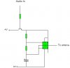
So i got a idea of a litle AM transmitter!

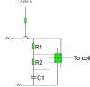
The timer wod oscilate on a freqancy thats on the am band and a transistor can define how much power the timer gets (audio input)

Can it work?

PS:
It wil be good to get rid of the inductor in a transmitter
 

Attachments

  • 555_transmit.jpg
    555_transmit.jpg
    11.9 KB · Views: 932
You need a coil to radiate the RF signal and it also comes in handy to add a variable capacitor for tuning.

Use pin 2 (trigger) to modulate the signal from the 555 oscillator.
Heres a link to a schematic of a 555 AM tranmitter, about halfway down the page. Replace the first 555 with your audio amp to modulate the carrier.

http://www.williamson-labs.com/555-tutorial.htm
 
What abaot if i conect the "To antena" thro coil to 0V ?(my circut)
Can that then work? :?

I think the two 555 timers are just to make the sound to transmitt!
And the coil and the capacitator modulate the signal!

So why wod be the C varible!(anser: To set the transmiting freqency)

I want the 555 timer to modulate
 
What abaot if i conect the "To antena" thro coil to 0V ?(my circut)
Can that then work?

Yep worth a try.


I think the two 555 timers are just to make the sound to transmitt!
And the coil and the capacitator modulate the signal!

From looking at the schematic it appears to me that the 555 on the left generates the RF carrier and other 555 is used as a PWM modulator in which the modulating audio signal is entered via pin 5 ( control voltage).
The coil and and variable cap is for tuning the transmitter to a particular RF frequency on your AM radio.


So why wod be the C varible!(anser: To set the transmiting freqency)

Yep looks about right. So like you suggested if you use a coil between the antenna and ground, the transmitter will radiate alot of harmonics and you would pic up the signal at several places along your AM radio dial.
 
OK! so far,so good! :D

Now i need the resitor values so it modulates on a right feqency!
Where cod i get that?

PS:
How do you get rid of harmonics and what are they?
Do you have any ideas to inprove somting?
 
ok i finaly got evrithing! :D

I think it givs out a 800-900 KHz on the 3 pin with the values:
R1 = 4.7 K
R2 = 78 K
C1 = 10 pF
V+ = 9V 150mA (a transformer)

Am i right?

Now i just need to build it!

Will it work?

PS:
What are harmonics?


Plese some replys!!!! :?
 

Attachments

  • 555_transmit1.jpg
    555_transmit1.jpg
    23.7 KB · Views: 676
This is the circuit in simulation.

as you see the oscilloscope is showing what is going out of the transistors emiter.

Is the signal modulated right?(on oscilloscope)

Signal:
Carrrier: 900 KHz
Modulated tone: 500 Hz
 

Attachments

  • Transmitt_555.jpg
    Transmitt_555.jpg
    120.4 KB · Views: 747
This is the circuit in simulation.

as you see the oscilloscope is showing what is going out of the transistors emiter.

Is the signal modulated right?(on oscilloscope)

The sim graph doesnt look right. The input signal looks like a 500Hz sawtooth type waveform and the carrier is oscillating 900 Khz and the graph shows the sawtooth signal riding on the higher 900 khz frequency, hows that possible ? The graph looks like an odd form of frequency modulation. For amplitude modulation the audio signal should control the amplitude envalope of the high frequency carrier, the transistor in your circuit appears to be controlling the output power instead.

Heres a suggestion:

Since your using a transistor why not build a simple Harley Oscillator and use the 555 timer to transmit in morse code ?
 
I found this am transmitter in the examples !

And its like mine but its flipt verticaly!
 

Attachments

  • transmitt_wave.jpg
    transmitt_wave.jpg
    127.3 KB · Views: 643
Status
Not open for further replies.

Latest threads

New Articles From Microcontroller Tips

Back
Top