Continue to Site

Welcome to our site!

Electro Tech is an online community (with over 170,000 members) who enjoy talking about and building electronic circuits, projects and gadgets. To participate you need to register. Registration is free. Click here to register now.

  • Welcome to our site! Electro Tech is an online community (with over 170,000 members) who enjoy talking about and building electronic circuits, projects and gadgets. To participate you need to register. Registration is free. Click here to register now.

Soldering station

Status
Not open for further replies.

123mmm

Member
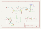
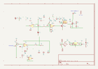
Hello ! I found on the internet the attached soldering station schematic and I wanted to know if this schematic is good for a basic soldering station with 50W/24V soldering iron which uses K type thermocouple.
I find that the LM358 which is used a thermocouple amplifier is not the best for this application, but I think that it is better than nothing.
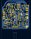
I also attached the pcb layout in Kicad.
Please have a look at the project and tell me what you think ?
 

Attachments

  • Screenshot .png
    Screenshot .png
    73.9 KB · Views: 174
  • schematic.png
    schematic.png
    139 KB · Views: 214
The power control part looks like a "burst file" type system which could work well.

The thermocouple part is not good.

To be accurate, a thermocouple needs to be wired with the correct, matched, wire type and connectors all the way to the amplifier. Any dissimilar metal joints or junctions will act as other thermocouples and affect the reading.

For full accuracy you should use a purpose made thermocouple converter IC (for that specific thermocouple type) that has the cold junction compensation built in, with the final thermocouple cable connections made as close to that as possible.

The circuit as show will presumable work but the temperature regulation will probably not be very good, as it will vary as the ambient temperature or the temperature of any unmatched wire connections used for the thermocouple change.
 
This is an example thermocouple converter IC on a breakout board - you could add something like this if you found the temperature was not stable enough:
 
I wanted to ask how can I check if hysteresis at the U1A (LM393) comparator can be verified if it is working correctly ?
More exactly, I found on the internet the following website: https://www.analog.com/en/analog-di...g-comparator-instability-with-hysteresis.html
But I don't know how to calculate the voltage on the inverting input and non inverting input of U1A.
Could you please give me an idea from where to start when calculating the hysteresis ?
 

Attachments

  • schematic.png
    schematic.png
    139.2 KB · Views: 161
Last edited:
The ratio of feedback to input resistors is 100:1 so the hysteresis will be roughly 1/100th the output voltage swing.

That is limited to less than 0.6V, the difference between output "low" state voltage and output off voltage, when Q1 base-emitter voltage limits the high level.

At a guess, around 0.5V swing.

1/100th that is about 5mV

U1B is used as an oscillator, creating a continuous sawtooth waveform.

U1A switching duty cycle will depend on the voltage from the thermocouple amp; as that varies, U1A will switch at that level of the sawtooth, varying the on-off duty cycle.

The hysteresis level is tiny in comparison to the sawtooth voltage, just enough to give clean switching and prevent oscillation.
 
Status
Not open for further replies.

Latest threads

Back
Top