Electro Tech is an online community (with over 170,000 members) who enjoy talking about and building electronic circuits, projects and gadgets. To participate you need to register. Registration is free. Click here to register now.
Welcome to our site! Electro Tech is an online community (with over 170,000 members) who enjoy talking about and building electronic circuits, projects and gadgets. To participate you need to register. Registration is free. Click here to register now.
Hi
Hoping someone can help.. I'm replacing a part on a PCB board which has blown a leg off. I've never done set on before, do I need to clean it out or can I just solder on top?
Thanks
Mike
The remaining pads need to be cleaned properly.... if you follow the damaged trace, it goes to the right hand pad of C19.
You could solder a new U6 on the PCB, then solder a jumper wire from pin 4 to the right hand pad of C19. (Along with adding a new C19)
Hi
Thanks for the reply, yeh blown off was the wrong words.. I had to replace a large capacitor in the middle and it was stuck to it. Do you know what C19 is?
Hi
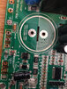
Yeh just realised I must have broken it when I took U6 off. This is a picture of it before it broke. In regards to U6 I had a nightmare trying to identify it, it broke when i took it off. But I could just make out the 73711 and managed to work out it was the component ive ebay linked.
**broken link removed**
Regards
Mike
Just one last question, I'll leave you in peace then.. what's the best way to have a good guess at the voltage rating of the capacitor... It's a 220v AC supply coming in which is then converted to DC and that powers a 180v DC motor.. but there's also small internal DC voltages for the speed up and down and to power the screen etc
The pad for pin4 on the board looks as though its been torn off, you'll need to repair that, maybe a piece of copper wire soldered to the track after scraping off the green solder resist will do the job.
I would clean all the old solder off with desoldering wick, then solder on the new chip while holding it down with something like blu tack, doesnt matter is you bridge the pins with solder as you can then go back with the desolder wick and remove the excess.
Find some old e waste and have a practice first.
The datasheet schematics are just examples of how the device can be used in a particular application. We do not know the voltage used in this circuit until we can either reference it on a schematic, or trace it back to the source on the PCB. (This is something you have to help us with)
Ceramic capacitors should be derated by 50%, meaning that if the supply voltage is 10V, the capacitor should be rated to at least 20V.....the closest ratings to 20V are 16V and 25V. Obviously, 16V is below, so the next value which is above 20V, would be 25V.
If the supply voltage is 12V, twice that is 24V and it might be better to step up to the next value, which is 35V.
In your other threads, you indicate that you have measured 10V and 15V at some points on the PCB, and it may be that this section of the PCB is indeed supplied with 10V or 15V, but in order to correctly verify, this particular section should be checked with a volt-meter, or visually traced back to the source.
Please understand that we do not have the PCB in front of us, so we are reliant upon the information that you can provide us.
I can't get a schematic for this board, I've tried and tried. The 15v and 10v were coming out of the yellow transformer going to the connection to the screen. The parts that's leg has been pulled off is at the other side of the board. Where the voltage comes out of the big bridge rectifier. The capacitor next to the part is rated at 50v, could that be an indication?
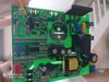
The power supply for U6 gets to this section of the PCB at the left pad of D8. (Red arrow pointing upwards in the pic)
You can see the vias going to the underside of the PCB.
There is a trace that runs along the underside of the PCB and comes back to the topside through a via beside one of the 3 electrolytic capacitors, which are close to the large one you have removed. (Red arrow pointing downwards in the pic)
Where it goes next, is for you to find out with your meter. It may go to one of those electrolytic capacitors, and it may not...
What are the devices circled in red? Are they voltage regulators and does the trace go back to one of those?
Hi
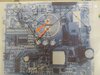
I've crudely drawn over a print out with most of the connections.. I've put arrows where those 2 traces come out. I've taken close ups of the components you asked about. They appear to be linear voltage regulators? But I'm not sure and no results come up for the numbers on them
Just one last question, I'll leave you in peace then.. what's the best way to have a good guess at the voltage rating of the capacitor... It's a 220v AC supply coming in which is then converted to DC and that powers a 180v DC motor.. but there's also small internal DC voltages for the speed up and down and to power the screen etc
There is an internal 24 volt Zener between pins 1 & 4. That would indicate that voltage between pins 1 and 4 will never exceed 24 volts as long as the part is not fried. Therefore, a 50 volt ceramic cap should be just fine.
Order today, ships today. C0805C104M5RAC7800 – 0.1 µF ±20% 50V Ceramic Capacitor X7R 0805 (2012 Metric) from KEMET. Pricing and Availability on millions of electronic components from Digi-Key Electronics.
www.digikey.com
Eyeballing the size of C19 against U6, it looks to be 0805.....
Order today, ships today. C0805C104J5RAC7800 – 0.1 µF ±5% 50V Ceramic Capacitor X7R 0805 (2012 Metric) from KEMET. Pricing and Availability on millions of electronic components from Digi-Key Electronics.
Order today, ships today. 06035C104JAT2A – 0.1 µF ±5% 50V Ceramic Capacitor X7R 0603 (1608 Metric) from KYOCERA AVX. Pricing and Availability on millions of electronic components from Digi-Key Electronics.
This site uses cookies to help personalise content, tailor your experience and to keep you logged in if you register.
By continuing to use this site, you are consenting to our use of cookies.