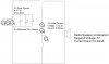
The capacitor ain't gonna buy you much; maybe a few seconds of playing time if the sun goes behind a cloud. If, as you say, this is mainly for amusement's sake, just let it fade in and out. You'd need a much bigger cap (probably a supercap) to do any real good there.
And as Audio McDuck pointed out, the capacitor goes in parallel with the batteries.
By the way, your JPEGs are a huge improvement over your PDFs!
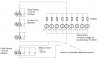
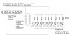
So far as your overly-complicated solar light circuit goes, it's a real mess. Obviously you're limiting yourself here to stuff you already have on hand. But if you were designing this from the ground up, you'd want all the solar cells grouped together as one source, and all the battery cells grouped together as storage. As it is, you're trying to run heterogeneous stuff in series, which while it's not dangerous or anything, it's certainly not efficient and you'll end up throwing away precious power.
But hey, it might just work ... actually, on second look, there's a major error in your design. You have several current sources (batteries of differing capacities) placed in series. That's no good. The "stronger" cells (the ones with higher mAh ratings) will be trying to force excess current through the "weaker" ones.
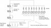
You really, really want all your batteries (with the same voltage rating, obviously) to be placed in parallel to form a bank of storage. Is this so hard to do? Since you're going to all this trouble, how hard would it be to just take everything apart and reassemble it in a better configuration?