Continue to Site

Welcome to our site!

Electro Tech is an online community (with over 170,000 members) who enjoy talking about and building electronic circuits, projects and gadgets. To participate you need to register. Registration is free. Click here to register now.

  • Welcome to our site! Electro Tech is an online community (with over 170,000 members) who enjoy talking about and building electronic circuits, projects and gadgets. To participate you need to register. Registration is free. Click here to register now.

Soil Moisture Reader/ Ohm Meter (detailed)

Status
Not open for further replies.

Michibacy

New Member
Hi Folks, It's been awhile since I did much circuit work so my apologies if I sound ignorant.

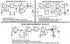
The concept is below, and any help designing it would be beyond appreciated :)

This project is in essence an ohm meter with some odd specifications.

Preferably ran off of 5VDC via USB charger in a cigarette lighter.
Wired
low power consumption

  1. In need of a basic circuit is in essence an ohm meter. Preferably an array of ohm values, where if the probes are inserted into soil that has 80% moisture, a blue LED turns on that notifies the driver the soil is too wet, if the probes are in contact with soil that is 55% moisture, a green LED lights up to let the driver know the soil is in the optimum moisture range, and if the probes come in contact with soil that is say below 40%, a red LED turns on letting the driver know the soil is too dry.
  2. I need a circuit that "blinks" (turns on and then off_ the voltage through Electrode 1 - through the soil with moisture content (what ever %) into Electrode 2. I have the electrodes which are a specially designed galvanized probe used in agriculture. I need 5 volts to pulsate through the probes using a potentiometer (preferably not a 555 Timer if possible). The rate of blinking will be adjusted depending on the speed of the tractor. The reason for needing to "blink" the voltage is to reduce the amount of electrolysis that is common when doing moisture reading with DC voltages
Any help is appreciated, thanks :)
 

And most of them are pure crap!

It is absolutely essential that the electrodes used in the earth are stainless steel, and the circuit must be an AC Ohmmeter with low amplitude (<1Vpp) AC-coupled excitation; not a DC circuit. The slightest amount of DC applied to the electrodes will cause electrolysis and oxidation of the electodes.
 
And most of them are pure crap!
I know. But I'd prefer it if the OP had made some basic attempt at looking up a relevant circuit, at least then he could ask us for the pros / cons of each approach or ways to improve / adapt them.
 
I don't mean to come across rude, so my apologies if I do.

I've been searching for 3 weeks now, I have a circuit building book from Radio Shack that's about 150 pages long that I've read from cover to cover, I've consulted with a guy who's been working on circuits for 40 years, I've searched this forum and other forums, utilized google and did as much self teaching as I could to do, to come up with this circuit as I can see it must be relatively simple. I am a newb when it comes to circuitry which I understand is a limiting factor when this isn't my profession, and I haven't taken course upon course on designing circuits.

I came here as a last resort because everything I come up with either tells me to use an ammeter or arduino. The ammeter will not give me the results I need and the Arduino goes against the concept of the project which is to produce a relatively simple machine that doesn't have processors that can go haywire.

If this isn't something I can get help with, I will go elsewhere, my apologies if I shouldn't be asking for beginners help...
 
Your in the right place and this is definitely something you can achieve. I just prefer it when the OP has done some research, which as you describe you have done.

So my approach (and some will disagree) would be to keep it simple to start off with as this is your first circuit.
So I'd suggest a 555 timer to switch the voltage (I know you said you didnt want to use one, by the way why is that?)
then I'd use a current sense resistor with an instrumental amp to measure the voltage across the resistor.
And a ADC to identify the different levels and enabled or latched by the 555 timer

this circuit will be quite prone to noise


so that's a start point for you, people WILL rip this circuit apart because there are far better engineers here but it helps to have a start point
 
Hi Mich.... Some years ago ... ( all my posts start like that :) ) I built a kit for sensing soil moisture, think it was designed for a plant pot works very well, does not seem to corrode the probes , they are just a split plated area on the point , the led flashed when it dries out set by the trimpot, I am going to use it or the circuit for my greenhouse environment controller , ( work in progress ) I have not got circuit so will have to reverse engineer it ( not a huge task ) will post here if useful... ( no names on board but chip is a really expensive and complex 74HC00 ;) )
moist01.jpg
 
Michy... this topic has come up many times on these forums. Use the Search-box above, and put in the key words: measure moisture

Lots of ideas here...

I just looked at another similar forum I write for. You might do the same search there...

Trust me, throw out any circuit that doesn't have a DC blocking capacitor in-series with the probes, and claims to measure AC impedance of the soil. I have tried the DC circuits and they are not stable/repeatable as a layer of crud builds up on the electrodes.
 
Last edited:
If you want this to operate for long periods in the soil then stainless electrodes are a good idea, also some means of switching the polarity of the electrodes so effectively ac is present on them, to reduce the effects of electrolysis.
I'm sure I've seen such circuits on the net.
What have you against the 555?, its a staple in many circuits like this, unless you use a programmable device.

I have one in my front room, it came from the pound shop, if it isnt dark out and the plant soil is dry it bleeps every minute to tell you to add water.
 
...I have not got circuit so will have to reverse engineer it ( not a huge task ) will post here if useful... ( no names on board but chip is a really expensive and complex 74HC00 ;) )
Might be similar to this:
 
I used 308 S/S welding rods for similar purpose, a 7555 based EC meter for hydroponics. All about conductivity.
Have a look at the EagleCAD files attached, the frequency output is governed by the conductivity of the medium. The caps provide the A.C. component.
 

Attachments

  • ECmeter.zip
    13.5 KB · Views: 291
A couple of questions:-
1)
The rate of blinking will be adjusted depending on the speed of the tractor.
Are you intending to make continuous moisture measurements by using probes dragged through the soil? If so, a major problem will be maintaining a fixed area of probe surface in contact with the soil.
2) Soil conductivity/resistance depends strongly on mineral content as well as moisture. How will you account for that?
 
Reading the original post again... ( admit i skipped a bit ) I would think your better option would be some non contact method such as the colour of the soil usually darker = wetter . as Alec posted sticking moving probes into the soil aint gona work .
 
The circuit from Red Circuits uses an ordinary CD4093 Cmos IC with a minimum supply of 3.0V. The battery is 3V only when new so the circuit is not reliable. When I fixed the original circuit a little more than 10 years ago I replaced the CD4093 with a SN74HC132 (different pins numbers) that is guaranteed to work when the supply drops to only 2.0V.
 
If you want a reliable sensor, you need an AC signal to measure capacitance of the soil as water has a large dielectric constant (~80) and influences the result better than DC resistance.

The problem with DC is that salts and acidic fertilizer from Nitrogen, Potash and Potassium drops the soil DC resistance so much that you can't always tell; Both moisture and fertilizer lower the DC resistance, but not the AC capacitance.

Capacitance is just passing like an audio range signal thru the soil and detecting the current with the voltage drop on a large series resistor. Then by rectifying the AC voltage with a diode + small cap to get DC then a high impedance comparator or Shmitt trigger like the SN74HC132. A pot will still be needed to set the reference resistance to match dry soil for a fixed SS probe pair.

The reason SS probes are used is to prevent corrosion and for DC to prevent galvanic reactions. ( battery effect with salts and acid in soil)

The circuit is still pretty simple, but I dont have one handy.
 
Here are three circuits that put AC on the probes. Mine is the second one that dims the LED so it is off when the soil is damp and blinks brighter and brighter as the soil becomes dry.
 

Attachments

  • Plants circuits.PNG
    Plants circuits.PNG
    10.2 KB · Views: 702
Here are three circuits that put AC on the probes. Mine is the second one that dims the LED so it is off when the soil is damp and blinks brighter and brighter as the soil becomes dry.

Component values?
 
I did not copy the component values for the first RED circuit because it had problems. Red's latest circuit has parts values on the Red website.
Here are my corrections to Red's original circuit:
 

Attachments

  • Plants_project.doc
    470.5 KB · Views: 362
I did not copy the component values for the first RED circuit because it had problems. Red's latest circuit has parts values on the Red website.
Here are my corrections to Red's original circuit:

You can drive the LED direct from Gate at 5V as ESR ~ 150Ω and use version II
 
You can drive the LED direct from Gate at 5V as ESR ~ 150Ω and use version II
RED CIRCUITS Version II uses an ordinary CD4093 Cmos gate IC and uses a 3V battery. When the battery voltage drops below 3V (it will drop to below 2V) then the CD4093 does not work. If you increase the supply to 5V (but a battery does not produce 5V) then the typical output current of the CD4093 gate will be only 3mA which is very dim. The current will be only 3mA because datasheets from Texas Instruments show it and the ESR calculates to be 1067 ohms, not 150 ohms.

My idea is to replace the CD4093 with an SN74HC132 that works with a supply as low as 2V and uses extremely low current when it is not driving an LED. With a 3V supply a 74HC gate can produce enough current to destroy an LED so a series current-limiting resistor must be used.

I made some LED chasers using a 3V battery that drops to 1.5V and an SN74HC4017 driving them. With 1.8V red LEDs I used a 22 ohms resistor to reduce the current to about 24mA. The circuit still works when the battery drops to 1.5V. To allow two AA alkaline cells to last for 3 months my circuit blinks each LED for only 30ms and chases around and around a few times then has a pause of a couple of seconds before chasing again.

I made some similar LED chasers using 3.5V blue and bright green LEDs powered from a 6V battery with four AA alkaline cells. Their LEDs are very bright for 3 months then still work when the battery has dropped to 3V.

I replaced all the battery cells in my chasers in the middle of December and again in the middle of March. Since all Target stores are closing soon in Canada I bought many Energizer AA alkaline and Ni-MH cells at very low prices.
 
Last edited:
Status
Not open for further replies.

Latest threads

New Articles From Microcontroller Tips

Back
Top