Continue to Site

Welcome to our site!

Electro Tech is an online community (with over 170,000 members) who enjoy talking about and building electronic circuits, projects and gadgets. To participate you need to register. Registration is free. Click here to register now.

  • Welcome to our site! Electro Tech is an online community (with over 170,000 members) who enjoy talking about and building electronic circuits, projects and gadgets. To participate you need to register. Registration is free. Click here to register now.

Software PWM

Status
Not open for further replies.

swapan

Member
Friends,

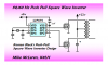
I am trying to develop program that will drive the MOSFETs of two channels of an Inverter/UPS. The complementary pulse width to each channel will be modulated depending upon the output of the UPS. I like to use software PWM utilising TMR, Interrupt etc. Please give some tip/hint or any link where I can have some idea on it.

The output of the UPS is square wave and frequency is 50HZ.

Swapan
 
Set TMR to rollover 5000 times a second (5000Hz). In the ISR increment a counter from 0-99. Have a variable for each channel containing a trip value representing the desired PWM duty cycle. Once that trip level is reached turn off the channel output. When the counter reaches 99 reset it to zero and turn the channel outputs high again.
 
Set TMR to rollover 5000 times a second (5000Hz). In the ISR increment a counter from 0-99. Have a variable for each channel containing a trip value representing the desired PWM duty cycle. Once that trip level is reached turn off the channel output. When the counter reaches 99 reset it to zero and turn the channel outputs high again.

Maybe you could show an example of this code?
 
The OP didn't mention their preferred programming language or compiler but here's a simple C example.

Code:
void isr 0 (void){
	if(TI0F){				//5000Hz  - Set Registers And Choose Appropriate Clock Source
		if(PWM==100){
			PWM=1;
			ChannelOne=1;
			ChannelTwo=1;
		}
		if(PWM > ChannelOneDuty){	//ChannelOneDuty Contains The Duty Cycle, 1=1%, 50=50% Etc.
			ChannelOne=0;
		}
		if(PWM > ChannelTwoDuty){
			ChannelTwo=0;
		}
		PWM++;
		TI0F=0;
	}
}
 
Last edited:
Many thanks LTX71CM for your reply. Really, I have made a mistake by not mentioning preferred language. I use MPLAB IDE and not conversant with C. So if you kindly post the program in assembly language it would be of immense help for me.

Swapan
 
Code:
void isr 0 (void){
	if(TI0F){
		if(PWM==100){
			PWM=1;
			ChannelOne=1;
			ChannelTwo=0;
		}
		if(PWM > ChannelOneDuty){
			ChannelOne=0;
			ChannelTwo=1;
		}
		PWM++;
		TI0F=0;
	}
}

EDIT: swapan, sorry but I stick with C, it will be up to you or another forum member to help you with an assembly version.
 
Last edited:
swapan,

What kind of a circuit are you using Sir? Something like this (below) which would drive one or the other MOSFET during alternating 10-msec half-cycles?

Regards, Mike
 

Attachments

  • RB Sine Wave 2.PNG
    RB Sine Wave 2.PNG
    18.5 KB · Views: 341
Then I don't think LTX71CM's approach is going to help you...

Can we Forum members brain storm this (give it some careful thought) and get back to you Sir?

Cheerful regards, Mike
 
Last edited:
swapan, do you understand the theory (Zero-error 1 second timing algorithm - about halfway down) and just need code help or do you need help with both aspects?

LTX71CM,

Please don't take this the wrong way but do you understand what he's trying to do? Generate two PWM square wave signals, one for each half of the 20-msec 50-Hz cycle? I only ask because your example code didn't really come anywhere near the target.

Kind regards, Mike
 
Until now, apparently not. How I read the original post left a different task in mind. Your statement of the problem made the objective clearer for me, thank you.
 
swapan,

If I were doing this from scratch I think I might use a 32-MHz clock and 256 interrupts at 78.125-usec (625 cycle) intervals (using the CCP module and "special event" interrupts). Use a 7-bit pwm counter variable and a 7-bit duty cycle variable (128 step soft PWM) and simply toggle the output pin pattern mask at the end of each 10-msec half cycle. Something like this perhaps;

Code:
;
;  void interrupt()             // 78.125-usec "spcl event" irq
;  { pir1.CCP1IF = 0;           // clear CCP1 interrupt flag
;    if(ctr.7)                  // if 10-msec half cycle
;      pinmask ^= 3;            // toggle output pin mask
;    ctr.7 = 0;                 // ctr %= 127 (unconditionally)
;    shadow = PORTB | pinmask;  // set shadow pin 'on'
;    if(ctr >= dcy)             // if pwm ctr >= duty cycle
;      shadow ^= pinmask;       // set shadow pin 'off'
;    PORTB = shadow;            // update port pins
;    ctr++;                     // bump pwm counter, 1..128
;  }
;
;  interrupt interval = 78.125-usecs (625 cycles @ 32-MHz clock)
;
;  7-bit (128 step) soft PWM
;
;
        bcf     PIR1,CCP1IF     ; clr CCP1 "special event" irq    |B0
        movlw   b'00000011'     ;                                 |B0
        btfsc   ctr,7           ; half cycle? no, skip, else      |B0
        xorwf   pinmask,F       ; toggle output pin mask          |B0
        bcf     ctr,7           ; ctr %= 127 (unconditionally)    |B0
        movf    dcy,W           ;                                 |B0
        subwf   ctr,W           ; C = 1 = (ctr >= dcy)            |B0
        movf    PORTB,W         ;                                 |B0
        iorwf   pinmask,W       ; turn output pin bit 'on'        |B0
        skpnc                   ; ctr >= dcy? no, skip, else      |B0
        xorwf   pinmask,W       ; turn output pin bit 'off'       |B0
        movwf   PORTB           ; update port pins                |B0
        incf    ctr,F           ; bump pwm counter, 1..128        |B0
;
 
Last edited:
I'd like to point out that Mike's words are gospel.:D
His assistance has helped me grasp asm.

Based on the sample circuit shown, I think you will get some RFI ringing from those MOSFETS which could be a problem for nearby low frequency wireless systems and possibly cause some spikes on your output. If this is for commercial use it will probably not pass EMC testing.

I draw your attention to section 2.4.4 in this pdf.
https://www.electro-tech-online.com/custompdfs/2010/09/szza009.pdf

best regards
 
Status
Not open for further replies.

Latest threads

New Articles From Microcontroller Tips

Back
Top