Electro Tech is an online community (with over 170,000 members) who enjoy talking about and building electronic circuits, projects and gadgets. To participate you need to register. Registration is free. Click here to register now.
Welcome to our site! Electro Tech is an online community (with over 170,000 members) who enjoy talking about and building electronic circuits, projects and gadgets. To participate you need to register. Registration is free. Click here to register now.
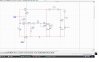
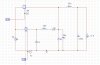
Any reason why using both IGBT and N-channel Mosfet?
I'll bet on that using a N-channel mosfet will provide less performance as there will be some voltage drop (much like an emitter follower for a bjt transistor).
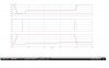
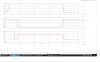
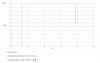
actually i have simulate the circuit and get the output..
but I'm not very sure about the waveform..
could anyone help me??
whether my waveform is right or wrong...
You should two different drive signals in your schematic. Are they really the same drive or are they different levels and phase or something? Do you have a plot of those two signals?
actually the drive signal for both switch is in the first attachment-pulse..
the auxiliary switch will on first than the main switch will on..
Vr in attachment refer to auxiliary switch
Vm-main switch..
I was not really understand about soft switching part in this circuit..
how to know the circuit operation on their mode..
Well, if you want someone to see if your waveforms are right then you have to provide the details that will allow this kind of check. For example, what is the delay between one drive signal and the other? Also, what is the amplitude of the drive signals?
This site uses cookies to help personalise content, tailor your experience and to keep you logged in if you register.
By continuing to use this site, you are consenting to our use of cookies.

")