aljamri
Member
Hi again,
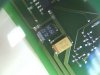
Attached is a photo for a similar component to a blown one in a faulty card I'm trying to repair. As an prehistoric technician, I'm not much familiar with SMD so, I do not know what are these two components.
I do contact EBCOS company and amazingly, the swift reply me, the yellow one is " tant chip capacitor" when I asked about its value and the identity of the black component, they gently excused that they can not help me.
Any body can help for the value of the yellow capacitor and the identity of the black one.
Thanks