Continue to Site

Welcome to our site!

Electro Tech is an online community (with over 170,000 members) who enjoy talking about and building electronic circuits, projects and gadgets. To participate you need to register. Registration is free. Click here to register now.

  • Welcome to our site! Electro Tech is an online community (with over 170,000 members) who enjoy talking about and building electronic circuits, projects and gadgets. To participate you need to register. Registration is free. Click here to register now.

Small soler cell question

Status
Not open for further replies.

nyoo

Member
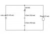
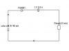
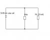
Really basic question, I'm afraid. I'd like to use a solar cell (3V, 45 mA in the midday sun) to power a small circuit. The circuit uses about 3V, 18-22 mA.

1. Is it true that power from solar cells must be stored or used immediately? A battery will give you from its store what you ask for (22 mA) and no more? But with a solar cell, you have to dispose of all the current it's generating?

2. If so, where do you put those extra unwanted milliamps? Put 1-watt resistor in parallel with the load to dissipate it as heat? Or a capacitor that will discharge in 12 hours? Add a physical earth/ground?

Grateful for the help.
 

Attachments

  • solar.JPG
    solar.JPG
    5.3 KB · Views: 198
Last edited:
The specs on a solar cell are limits it can't go over. If your solar cell can't go over 3 volts and the load is designed for 3 volts, you don't have a problem. Just to make sure, you can connect a volt meter to watch the voltage being applied to the load. Just to make sure, you can add a 3.3 volt zener diode across the load so the solar cell can't push more than 3.3 volts or the zener diode will eat the excess. A 1/2 watt zener will be safe in this condition with no resistors to "save" it.
 
I just remembered, there is an article on this site that basically says the amps, or in your case, milliapms, don't jump out and force themselves to go through the load. They're just "available". It's the voltage that forces current to flow.

If you want to read it, just go to the top of this page and click on Home. It's called The amp-hour fallacy and it's on the first page.
 
Small solar cell question

For a storage device, like a AA battery or your local electric company, it makes sense: you pull from them only as much current as you need.

But for a system that's generating power, be it a 45 mA solar cell or a hydroelectric plant, does it just stop generating if nobody is asking for the current?

Thanks.
 
Last edited:
Your local electric company IS a running generators. They are connected to the wires to your house. The voltage only pushes as much current as you need through your appliances.

Your car battery can supply 300 cold cranking amps, but it doesn't shove all 300 amps through your headlights because it only has 12 volts to push with.

I could copy that article here, but it would be easier on my typing finger if you read it on the Home page.
 
Hi nvoo,

I suggest to charge two 1/3AAA batteries of C=55mAh or two 1/3AA batteries of C=110mAh using the excessive current (23mA) the solar cell generates.

That way you might operate your circuit with no sunlight for several hours.

Use a low current Schottky diode (BAT85) to prevent discharging of the batteries into the solar cell when there is no sunlight.

Boncuk
 
Last edited:
Your local electric company IS a running generators. They are connected to the wires to your house. The voltage only pushes as much current as you need through your appliances.

Your car battery can supply 300 cold cranking amps, but it doesn't shove all 300 amps through your headlights because it only has 12 volts to push with.

I could copy that article here, but it would be easier on my typing finger if you read it on the Home page.

i too have the same feeling as that of u shared surprised how 2 different persons can have so similar thoughts .... lol ,


thermal imaging camera
 
Last edited:
Boncuk, thanks for the advice and the battery idea. Researching the BAT85.

The stored electricity won't be used, as the circuit will only run during the day. (The circuit answwers: "Send a radio message if you see the sun.") Could I just discharge the electricity as it's generated? What about a variable-speed fan?

DX3, thanks for your efforts and for the reference to the amp-hour fallacy. Yes, it was aimed at me, the guy trying to fix the tail light on his van.

My nearest power plant monitors how much electricity our county is using. If we're using less, they shut down a generator. If we're using a little more, they add another generator at half speed. I'm trying to do that with my meagre 45 mA.
 
The problem with a solar cell is its high internal impedance.
This means that when you want to take current from the cell, its voltage drops. Most electronic circuits take a varying current and although the average may be 22mA, it sometimes requires a much higher current for a short period of time.
That's why you need a large electrolytic across the supply, a battery or even a super-cap to store the energy so that the circuit you are driving, WILLL WORK.
 
See attached. Will this work?

But I want the 1/3AA batteries to discharge overnight to 10% full, don't I?
Does the Schottky diode prevent that overnight discharge?
 

Attachments

  • solarcell2.JPG
    solarcell2.JPG
    8.3 KB · Views: 197
Last edited:
1. A 3v solar cell will never be able to charge 2 1.2 or 1.5v cells.
2. A super-cap is permanently connected to the micro.
3. A diode is placed between the solar cell and a super-cap.
4. A sense line is taken from the solar cell to the micro to detect when the sun shines.
5. The super cap will have sufficient energy to allow the micro to send a signal.
 
The two 1.5V batteries were not to charge. They were to absorb the excess current, and then discharge it. It that what you meant?

Does the attached schematic match what was suggested?
How big a supercap should I use to store (and discharge) a day's overage? I reckon about 125 mA per day.
Does the usual rule hold, voltage on the capacitor should be twice the supply voltage?
I'm discharging back into the solar cell, is that okay?

Not sure about a "sense line". I imagined the circuit will operate when there's current (i.e., sun), will shut down when there's none. Is there something more I should be considering?

Thanks for your help.
 

Attachments

  • solarcell3.JPG
    solarcell3.JPG
    6.3 KB · Views: 187
Last edited:
The two 1.5V batteries were not to charge. They were to absorb the excess current, and then discharge it.
Getting the two cells the "absorb" excess current is exactly the same as "charging" them. The cells produce a "floating charge" or "floating voltage" that is far higher than 3v and your solar cell will not be able to deliver any energy into them. That's why I suggested you use a super-cap.


Use a 0.22F super-cap directly across the project.
Take a "sense line" from the solar panel to the project to detect when illumination is present. The purpose of the super-cap is to allow the project to work at the first sign of illumination. The project will have to be able to shut down to less than 1mA.
 
A solar cell is an illumination based current source clamped by the inherent diode of the cell. Assuming silicon, the diode will begin to conduct at about 0.52 vdc at 25 deg C. As with a regular silicon diode it has a negative temperature coefficient so the hotter the cell gets the lower the inherent diode conduction voltage gets.

There is some series resistance associated with collecting metal and bulk silicon conduction. Depending on the quality of cell there can be some parallel shunt leakage resistance The shunt resistance usually does not become a factor until the illumination is low and there is not much current generated.

As such your model of cell as a voltage source is not accurate. Cells are usually modelled as a current source (dependent on illumination) in parallel with a diode. At no load on the cell all the generated current will be shunted down the inherent diode. For a short circuit across the cell all the illumination current can be read by external ammeter.

The maximum power point is loading such that the inherent diode just slightly conducts, typically absorbing about 3% of illumination generated current. This provides the highest voltage possible without letting too much current to shunt down the inherent diode. This yields the highest power (V x I) output. Again, at 25 degrees C it is approximately 0.52 vdc. There is approximately a -2mV/degC temp coefficient to this voltage across temperature.

You do not have to operated at maximum power point. If the series stack of cells has a maximum power point voltage greater then battery voltage then the module can be place across a battery and the PV module voltage will drop to battery voltage. All illumination generated current will be fed to battery. The current will continue to flow (assuming illumination is maintained) and the battery will be charged at the PV module current output. Once the battery has reached its desired maximum charged voltage there should be a voltage based switch to disconnect the PV module from the battery to prevent overcharging the battery. It is also a usual practice to put a blocking diode between the battery an PV module to prevent battery discharging back through PV module when PV module has no illumination on it.

To get higher voltage, cells are stacked in series. If your module produces 3v at maximum power point then it has six cells in series. At no load the voltage gets a bit higher because the cell diodes are driven harder into conduction by the illumination generated current.

A 'AA' NiCad battery is about 500 mA/hrs, a NiMH will be up to twice this amount. Both can take a continous over charge of 50 mA's so you PV module should be able to be permanently connected (with a blocking diode). Max charging voltage will be about 1.4 vdc per cell or 2.8 vdc. You should use a hot carrier diode for blocking diode (about 0.3vdc drop) since your module may not have enough voltage if it only produces 3 vdc at 45 mA. A regular diode for reverse blocking will have about 0.7vdc drop only yielding about 2.3 vdc to batteries.

Further info at: **broken link removed**
 
Last edited:
Colin55, thanks. I will use a .22F supercap.

The concept of current source vs voltage source is beyond my skill, at this point in my apprenticeship. But I did get from the discussion that I should stop thinking of a solar cell in terms of a battery. DX3 said something like this, way at the beginning of the thread.

The circuit shall use a Schottky diode = hot carrier diode, for its low voltage drop.
If the series stack of cells has a maximum power point voltage greater then battery voltage then the module can be place across a battery and the PV module voltage will drop to battery voltage.

Does this also apply to capacitors? THe .22F supercap come in 2.5, 3.3, 5 and 5.5 volts. Can I use the 5.5V supercap, in light of this quote?

Advice seems evenly divided, though, NiMH battery vs. supercap.
 
Last edited:
You can't use a NiMH battery because it will not begin to charge until the voltage is above 3.6v. But a super cap will charge at any voltage it is supplied with. That's why you should use a 5v5 supercap. That's why you are listening to us. We are telling you things that you will never learn in 100 years from reading a book.
 
Knowing the load of what this solar cell must power is more important at this point than any other suggestions as they're random suggestions unless it's known. a .22F supercap will go from 3V to 1.6 volts in about 60 seconds with a 500ohm load. If the minimum voltage your circuit needs is 2 volts it'll be 45 seconds. A lot of digital circuits drop out around 2.7 volts which gives you about 10-20 seconds of holdup time. That's the thing that sucks about supercaps. If the voltage you need to maintain is high, you're only utilizing a small fraction of the stored charge available. in the case of 2.7 volts required to operate the circuit 75% or more of the charge actually stored in the cap isn't usable. To properly utilize the stored charge down to a volt or so you'd need a buck converter, which is only going to be 50-80% efficient.
 
Last edited:
Colin55, yes I agree with you 110%, without the expert advice of people like yourself in this forum I would never make any progress (or even any working curcuits). I'll be using your recommended .22F supercap. I was asking what voltage rating to use. Sorry I appear so inarticulate.
But a super cap will charge at any voltage it is supplied with.

Thanks for that.

Sceadwian, thanks for this information. A test confirms your suspicion. The drop-out voltage will be about 2.7 volts. I'm okay with a holdup time of 10-20 seconds. The circuit is intended to answer "send a radio signal to say the sun is shining".
 
Last edited:
That holdup time is only if the load is 500ohms, You said yours was 18ma so that's going to be about 5 second, but that's beside the point now, you said this circuit only needs to work if the sun is actually shining? If the sun is shining the panel is generation power which means you don't need the capacitor to hold anything up. A small capacitor for smoothing the power would probably be a good idea but a supercap is not needed.
 
Last edited:
The problem you have is this:
The panel will only produce a useable current when the illumination is very bright. If you want to detect when daylight has appeared, you will need some sort of stored energy to power your circuit, a bit like a garden light. These are $3.00 each in Australia and have a single AA rechargeable cell, a 2v solar panel and a voltage multiplier circuit that produces up to 5v.
This is the best option for you as the charging circuit can be used to power a microcontroller circuit.
See my website for the circuit I have designed to do this.
At least I provide practical answers to all the queries and not "armchair electronics" advice.
 
Last edited:
Status
Not open for further replies.

Latest threads

New Articles From Microcontroller Tips

Back
Top