Continue to Site

Welcome to our site!

Electro Tech is an online community (with over 170,000 members) who enjoy talking about and building electronic circuits, projects and gadgets. To participate you need to register. Registration is free. Click here to register now.

  • Welcome to our site! Electro Tech is an online community (with over 170,000 members) who enjoy talking about and building electronic circuits, projects and gadgets. To participate you need to register. Registration is free. Click here to register now.

Small Microphone/Speaker Circuit

Status
Not open for further replies.

bluethecow

New Member
I'm extremely new to building circuits etc, as I come from the high-level software world, so please don't flame me :).
I have a microphone and a speaker with plugs that connect to my computer's PCI sound card, and I want to build a small circuit to connect the two, separate of a PC, so that when sound goes into the microphone, it comes out from the speaker. I've read a bit about microphones and speakers and how they work, but I couldn't find much more information than that when searching, mostly because I'm not sure exactly what to search for. Can someone point me in the right direction?
 
You need a power amplifier to drive the speaker, a resistor to provide current to the microphone if it is an electret type and a battery or AC adapter for power.

Then if the microphone can hear the speaker they will howl due to acoustical feedback.

How loud do you want the speaker to be?
 
Thanks for your response.
I'm pretty sure I can find enough information to build the amplifier, but how can I figure out how much power I should provide to the microphone?
Also, how do I figure out if my microphone is electret or otherwise?

Thanks!
 
Last edited:
bluethecow said:
I'm pretty sure I can figure out enough to build the amplifier
An amplifier IC is the easiest, probably the cheapest and works the best.
Many people start with the LM386 power amplifier IC. It provides about half a Watt of power to an 8 ohm speaker with a 9V supply.

how can I figure out how much power I should provide to the microphone?
Microphones don't have power provided to them. An electret mic needs 0.5mA of current, not power. The speaker gets the amplifier's power provided to it. The loudness of the speaker is caused by the amount of power from the amplifier. If the power from the amplifier is too high for the speaker then the speaker will break.

how do I figure out if my microphone is electret or otherwise?
If it is slightly bigger than a pencil's eraser then it is electret. It will have two wires, one connected to its metal case which is ground in the circuit. The other wire gets a small positive DC current from a resistor and is its output.
 

Attachments

  • LM386 with mic.PNG
    LM386 with mic.PNG
    13 KB · Views: 5,194
Wow, lots of info!
I am curious though, would it be a good idea to add a pre-amplifier circuit using something like the TL084 (by Texas Instruments) before the LM386 shown in your circuit? Or would that make much of a difference?

Edit- By the way, please forgive me for the delayed replies; I googled extensively before my responses :).
 
Last edited:
bluethecow said:
Wow, lots of info!
I am curious though, would it be a good idea to add a pre-amplifier circuit using something like the TL084 (by Texas Instruments) before the LM386 shown in your circuit? Or would that make much of a difference?

Edit- By the way, please forgive me for the delayed replies; I googled extensively before my responses :).

yes, you can do this to increase the gain if necessary. You may want to breadboard the circuit above to see if it is adequate before adding the TL084.
 
I didn't feel it was necessary to start a new thread for this question-
I've been trying to figure out where I can get a DIP version of the TL084 chip by Texas Instruments (mentioned earlier in thread), but everywhere I look there are 8 to 18 week lead times. Does anyone know where (and if) I can get 1-5 of these chips within a reasonable amount of time (a few days to one or two weeks)?
 
Where are you located? It's always good to fill in the location field in your profile.

The 386 design Audioguru shows should be fine without preamplification as the 386 is set up to have a gain of 200 (increased from 20 by the 10uF cap between pins 8 and 1).

Here is the datasheet for the part. Although the half watt or so of power will produce a respectable sound level (a little higher than talking level without much distortion and with a reasonably efficient speaker) you may want more power depending on your application.

**broken link removed**
 
Where are you located?
Texas :D
Here is the datasheet for the part.
Yes, I saw the datasheet earlier, but there is one question I forgot to ask- between the LM386N-1 and N-3, the only difference seems to be the output power (Pout) under the Electrical Characteristics section. What specifically do those numbers mean? Does it mean the N-3 will amplify louder because it has more output power?
you may want more power depending on your application
I don't really need more power, but I want more just 'cause :). Its the Texan way.

Also, silly me, I forgot to check froogle for the TL084...
 
Last edited:
Last edited:
Not sure if you have tried this site yet
Well it wasn't the LM386 with which I had a problem with delivery time... National is nice and gives us free 24 hour samples, maximum of 5 units per sample and 5 samples per week, makes me all fuzzy and warm inside. :cool:
It was the TI TL084 that I was questioning, as I can't tell if the Lead Time applies to only large orders or samples as well, and the lead times were all from 4-24 weeks. I just didn't know so many companies distributed this stuff until I froogled it.
Once I get all the parts together I might take some pictures and post them here, just for the heck of it.
 
Last edited:
The TL084 is a useful part to have, but shouldn't be totally needed in this application (unless you need very high sensitivity). I edited my previous post btw after realising it was the 084 you wanted. Still not sure if there is a lead on it though.
 
You don't need a quad op amp (TL084). Try finding TL071 or TL081 (single), or TL072 or TL082 (dual).
 
The LM386 schematic I attached has a voltage gain of 200 which is plenty of gain. So an additional preamp will not be required.
 
You don't need a quad op amp
Am I right in thinking that a quad just acts like 4 singles, but in one chip? That's what it looks like from the documentation.
Am I also right in thinking that if I run the output of the first into the input of the second etc, that I could increase the voltage even more? Not that I need it, I just think it would be interesting to try.

audioguru said:
The LM386 schematic I attached has a voltage gain of 200 which is plenty of gain.
Definately! One thing I can't stop myself from asking is, what the heck does all that stuff do (the components in the circuit you posted)? More specifically as an example, why are there so many capacitors (I counted 6) and what exactly do they do in this circuit? I have no idea. I guess its not important to know the theory to build a circuit (at least from someone else's design), but it would be nice if I could understand it better. Is there a good book I can buy (or something) that explains these kinds of things? Sorry if I come off as rude (or extremely newbish, which I am), I just really want to get into this kind of thing, and I don't know much about it.
 
Last edited:
bluethecow said:
Am I right in thinking that a quad just acts like 4 singles, but in one chip?
Yes.

Am I also right in thinking that if I run the output of the first into the input of the second etc, that I could increase the voltage even more? Not that I need it, I just think it would be interesting to try.
The LM386 amp has a voltage gain of 200 which is a lot. An opam has a low frequency voltage gain of a few hundred thousand or a wideband voltage gain of about 300. Two cascaded give a wideband voltage gain of 90,000 which is so high that they will just amplify circuit noise.

what the heck does all that stuff do (the components in the circuit you posted)? More specifically as an example, why are there so many capacitors (I counted 6) and what specifically do they do in this circuit?
1) The 100uF cap filters the supply for the mic so that feedback doesn't occur.
2) The 1uF cap allows the mic to have its own DC voltage and allows the input DC voltage of the amp to be at 0V, and passes the audio.
3) The 470uF cap bypasses the battery and keeps a low impedance as the internal resistance of the battery increases as it runs down.
4) The 10uF cap increases the gain from 20 to 200.
5) The 0.05uF cap couples the 10 ohm resistor from the output to ground without passing the DC.
6) The 470uF output cap couples AC audio to the speaker but not DC.
 
audioguru said:
Two cascaded give a wideband voltage gain of 90,000 which is so high
Sounds fun ;)

4) The 10uF cap increases the gain from 20 to 200.
Fully understood :D.
2) The 1uF cap allows the mic to have its own DC voltage and allows the input DC voltage of the amp to be at 0V, and passes the audio.
Hmm, I think it makes sense :).
3) The 470uF cap bypasses the battery and keeps a low impedance as the internal resistance of the battery increases as it runs down.
I don't totally understand that (that is, I understand why it bypasses the battery, just not entirely how) :eek:. One specific question though, theoretically, could you remove that capacitor and just connect pin 2 to the negative terminal (gound) of the battery without drastic consequences?
5) The 0.05uF cap couples the 10 ohm resistor from the output to ground without passing the DC.
I don't quite see what it's doing :confused:. Also, what exactly does "couple" (as a verb) mean? I've seen it used frequently- "capacitively coupled", "couple the pot to", etc. but can't quite figure it out.
1) The 100uF cap filters the supply for the mic so that feedback doesn't occur.
I don't fully understand :confused:. Feedback from the speaker? Filter like an RC circuit?
6) The 470uF output cap couples AC audio to the speaker but not DC.
Erm, what? :eek: There's that couple word again :(. Does that mean the output from the amplifier is AC? Or..?

One general question covering all of the caps is this- why those specific sizes? I suppose the 1uF makes sense, but what about some of the others? Is it about the time it takes to charge them?

Thanks for your time, its really nice that you guys are helping!

Edit-Please forgive the excessive use of smilies to illustrate my levels of understanding, its for the visual people! :p
 
bluethecow said:
I don't totally understand that (that is, I understand why it bypasses the battery, just not entirely how)
The internal resistance of the battery increases when the battery runs down. Then the supply current changing in the amplifier when it is pulsing into the speaker causes the supply voltage to jump up and down. Then the whole circuit starts to jump up and down making a "put, put,put" sound. All battery operated circuits should have a supply bypass cap to supply peak current pulses when the battery can't.

One specific question though, theoretically, could you remove that capacitor and just connect pin 2 to the negative terminal (ground) of the battery without drastic consequences?
Pin2 is already connected to ground which is the negative terminal of the battery. The battery's voltage will jump all over the place without a bypass cap.

I don't quite see what it's doing :confused:. Also, what exactly does "couple" (as a verb) mean? I've seen it used frequently- "capacitively coupled", "couple the pot to", etc. but can't quite figure it out.

I don't fully understand :confused:. Feedback from the speaker? Filter like an RC circuit?
The speaker is an inductor. Inductors have a high impedance at high frequencies. The IC is designed to work with an 8 ohm load and goes crazy if the 10 ohm resistor is not its high frequency load. The 0.05uF cap couples the AC without passing the DC.

Erm, what? :eek: There's that couple word again :(. Does that mean the output from the amplifier is AC? Or..?
A capacitor couples an AC signal from one stage to another stage, or sometimes from the output of an amplifier to a speaker. Couple also means to pass.

One general question covering all of the caps is this- why those specific sizes? I suppose the 1uF makes sense, but what about some of the others? Is it about the time it takes to charge them?
A capacitor has impedance which depends on its value and on the frequency. The impedance of the 470uF output capacitor at 100Hz is 3.4 ohms so most of a 100Hz signal will go to an 8 ohm speaker, but at lower frequencies the cap will have a higher impedance and less lower frequencies will go to the speaker.

Thanks for your time, its really nice that you guys are helping!
Glad to help. We are just a bunch of really nice guys!
 
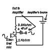
If you have an electret mic, try this:
 

Attachments

  • 1mic.jpg
    1mic.jpg
    15.5 KB · Views: 403
catcat said:
If you have an electret mic, try this:
I have seen millions of electret microphone circuits but none has your 1k resistor. It isn't needed and the mic might not even work if it is there. With the 1k resistor removed then the value of the other resistor should be increased to provide about 0.5mA to the Fet in the mic. 10k works for a 9V battery.
 
Status
Not open for further replies.

Latest threads

New Articles From Microcontroller Tips

Back
Top