Continue to Site

Welcome to our site!

Electro Tech is an online community (with over 170,000 members) who enjoy talking about and building electronic circuits, projects and gadgets. To participate you need to register. Registration is free. Click here to register now.

  • Welcome to our site! Electro Tech is an online community (with over 170,000 members) who enjoy talking about and building electronic circuits, projects and gadgets. To participate you need to register. Registration is free. Click here to register now.

Small charge controller for 6 V lead-acid battery with a 6 V 3 W module

Status
Not open for further replies.

edresch

New Member
Hello everyone,

I will work on a project with some students on small solar lanterns for rural electrification. My area of studies is actually batteries (I'm a process engineer), but somehow I get always involved in electrical engineering, since I'm working in the renewables field.

Anyways, my university has some small PV modules (amorphous 3 W 6 V Voc) and some small lead-acid batteries (6V 1.2 Ah) and also some high power WLED's. I would like to develop a project with a small number of students where they can create a small circuit to charge the battery / power the LED. I found already some circuits, but most of them use 12V panels. Should I connect my panels in series then? Or is there a way to use the 6V modules to charge the batteries?

Thank you very much!
 
Welcome to ETO!
Post (using the 'Upload a file' button) the circuit(s) you propose to use and we can see what modifications, if any, would be needed.
 
To charge a 6V lead-acid, it requires ~7.3V.

The panel must put out substantial current at 7.3V. It takes a panel with an open-circuit voltage >10V to do that, so it will take two of your panels in-series...
 
Thank you for the replies!

I was thinking about a circuit like the following:

**broken link removed**

Or something even simpler like this:

**broken link removed**

I would like to show the students how cheap solar lanterns could be built, so if there was a way I could adapt the second circuit it would be great. I would also use 2 panels in series then.

Thanks again!

e.dresch
 
Seems like you need the following:

1. Automatically stop charging when battery is fully charged. (To protect the battery)
2. Automatically turn off the light when the battery is xx% discharged. (To protect the battery, Lead acid should not be discharged to zero)
3. Optionally automatically turn on the light when the sun sets?
 
Hi Mike,

Exactly. I mean, I don't need to have a complicated charging procedure (I think it would be ok just to charge the battery with a I5 current till 2.4 V, no need for a constant voltage charging at 2.4 V). It's supposed to be something simple, but I also want to show the students that if they would like to treat the battery well so that it lasts longer, a more complicated circuit would be necessary.

I think for the discharge, a SOC-control would be great, but that might be also a bit more complicated, so I was really thinking about something like a voltage control. It wouldn't need to wait for the battery to be fully discharged at 1.8 V or something, something that turns off at around 1.9 V.

I will be talking a lot with them about quality control, so then I can point them what was wrong with our method of charging/discharging the battery.
 
I gave up watching the silly video with an absolutely HUGE and powerful solar panel charging a tiny battery with a very low current. My cheap Chinese solar garden lights ($1.00CAN each at WalMart) do the same with NO charging circuit.
They use a single Ni-MH AAA cell and a circuit that steps up the voltage to light the white LED. I add a diode and capacitor so it can operate a red, green and blue colors changing LED that I buy for $1.00CAN at The Dollar Store.
 
I think it would be ok just to charge the battery with a I5 current till 2.4 V, no need for a constant voltage charging at 2.4 V
Where did this figure of 2.4V come from? I thought we were talking 6V batteries?
 
I could show you an elegantly simply design with no regulators and 2 LED's per battery if you want to teach them skills on choosing a good mate between power source and load, power management with a switch to control brightness using a small Resistor and extend dim battery life and use the same PV arrays you have. Budget around $10 plus a luminare fixture.

depending on other skills you want to teach like, maximal power transfer between Solar panel to battery to LED, easy bake soldering skills for SMT, Thermal resistance, electrical resistance in LEDs and packaging design, colour quality and luminous efficacy ( like efficiency) I can prepare a list of materials and design that will make cheap garden lights look anemic.

However you could use the fancy $1 garden lights for Luminaires. but we would have to add a 1A MOSFET switch if you want it operated by darkness with your PV panel but that may be too much complexity but not that much.

Basically pimping your average $2 Garden light into a heavy duty flashlight or garden area light. You have to design the PV into your luminare, but a fixed fixture would be easier.
**broken link removed**
These give more than 50x your average garden light and the chip costs < a buck.
If you dont have good soldering skills then the Epistar comes pre-soldered to an aluminum board with solder pads. but cost much more.
 
Hi Tony,

yeah those are the LED's that I have too. A simple design without regulation could also be great. I still have some budget left to order some new things I would need. The other skills you mentioned would be great too, but I think I wouldn't have the time needed for it. I will also deal with the subject of how to market such solar lamps for developing countries, so I was thinking of having 1 full day of practical work.

Thank you
 
The slightly larger than AA LiPo cell called the 18650 cell available on Ebay or anywhere is possibly the best secondary battery match for the 3W LED. It is a bit higher than the primary Lithium Cell of 3.0
https://www.sparkfun.com/products/12895

ion2.jpg


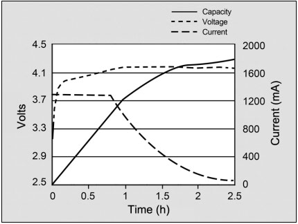
The simplest solution is charge with PV to 4.10~4.15 then stop charging by turning on the LED
When switched the LED is selected on a different connection to the battery as the voltage will drop when the charger has reached full charge.

We will use only a carefully selected Diode and R for both functions.

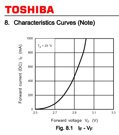
This LED response is only spec'd at 25'C which will lower in voltage as it gets hot. Heat loss must be mechanically design to reduce the heatsink resistance to <30deg C per Watt.

upload_2015-4-24_23-4-21.png

I won't get into details unless you show some thermal design understanding.
 
Here is one of many videos about wonderful 18650 batteries available on ebay:
 
  • n.b. I chose 2.90V where junction is saturated and fairly linear above this , which is almost 50% of the Absolute Max current and power of the device.

    Vth = 2.710 V , ESR = 0.400 ............ (3)


  • resulted iin error <1.8% in Vled


my error in digitizing Toshiba graphs ~1%
4362456700_1429970752.jpg


calculated Vled from (2) using (3) and I only.

V I ESR P Watt-Ω's Vled Error
2.70 0.08 2.00 0.216 0.43 2.742 1.6%
2.80 0.22 0.71 0.616 0.44 2.798 -0.1%
2.90 0.47 0.40 1.3659 0.54 2.8984 -0.1%
3.00 0.86 0.26 2.583 0.66 3.0544 1.8%


At the risk of being too verbose or too brief, do you follow my points yet?
 
I thought he was going to say it was cocaine used for Cartel and flour for Ebay.

He took a long time to discover this.. I would have estimate ESR on the battery and used this to achieve 1/2V more or less and then decide in 1 millisecond ( or <<1s) if it was a good battery or not.

2400mAh using C/10 = 240mA
But ESR is around 100 mOhm thus 3.6A so using 100 mOhm if you get 1.8V , its ok. if much less N.G.
Short cct current would then be 7.2A but will blow internal fuse or explode if no fuse.
If Isc is tested in << 1 ms you can also estimate ESR. Or use a known Rref.
 
Status
Not open for further replies.

Latest threads

New Articles From Microcontroller Tips

Back
Top