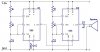
I have a schematic for a siren generator that I modified from a book.
I understand that the combination of the two 555 timers (one output connecting to pin 5 of the second) somehow produce a sine wave (AC signal)
What I don't understand is how this happens...
Can anyone explain this to me?
Thanks
I understand that the combination of the two 555 timers (one output connecting to pin 5 of the second) somehow produce a sine wave (AC signal)
What I don't understand is how this happens...
Can anyone explain this to me?
Thanks