Continue to Site

Welcome to our site!

Electro Tech is an online community (with over 170,000 members) who enjoy talking about and building electronic circuits, projects and gadgets. To participate you need to register. Registration is free. Click here to register now.

  • Welcome to our site! Electro Tech is an online community (with over 170,000 members) who enjoy talking about and building electronic circuits, projects and gadgets. To participate you need to register. Registration is free. Click here to register now.

single transistor audio amp

Status
Not open for further replies.

mamun2a

New Member
I Need a single transistor base economic mini audio amp.
 
mamun2a said:
I Need a single transistor base economic mini audio amp.

Why do u bothering with small transistor amps......for learning purposes like transistor biasing its good.......there are plenty economic audio IC's designed for mini audio...

You mentioned one transistor amplifier only give u power output about 0.5w..without going to a bigger transistor...or may be u asking a single transistor amplifier to reduce the space in the cct...

there are IC's designed from 5pin SIL,8pin DIPS .....giving a nice smooth outputs..having only few external parts.....& need only a small voltage & current.like KA 2209,TDA 2002....etc
 
Is this college work?

Do it yourself.
 
amplify with least parts
Then an IC (Which is one part) is the best route.
You don't mention how much gain or the output power level that you need. We need this info to give you a valid answer.
 
Then find an audio amplifier IC. A low power amplifier IC might have a couple decoupling capactors and a resistor or two. A single transistor amplifier could have a dozen or more supporting components.
 
It is possible to use a N channel power mosfet, connect the 4 ohm or 8 ohm speaker right between the drain and the + power supply lead. Biasing the gate to class A operation you could get some power out that way and it would be pretty sensitive.
 
That was my first audio amp and it was crap, the distortion was terrible and there was DC in the speaker so it got hot.

Anyway you haven't given any information.

Gain?

Power?

The attached schematic is a the simplist audio amp you can build.
 

Attachments

  • Small amp.GIF
    Small amp.GIF
    2.7 KB · Views: 1,933
Hi Hero,
I simulated your small amplifier.
1) With an 8 ohm speaker, it doesn't have gain, it has loss.
2) It has a very small output power, a whopping 0.8mW. Headphones have much more power.
3) It is distorted.

I also tried it as an emitter-follower and its loss is less. Its output power is 0.2mW.
 

Attachments

  • sim-amplifier.PNG
    sim-amplifier.PNG
    35.9 KB · Views: 1,202
Of course it won't power an 8:eek:hm: speaker (I'm insulted you would ever think that I'm so much of a noob that I didn't know it won't do that!) but where did he ever say he wanted to do that?

He just said he wanted an audio amplifier and this circuit will do just that.

He didn't say what gain he required, so I just designed one with a gain of 4.7.

I was proving a point, if you make a vague request then no one wil be able to give you what you want.
 
Alright then with a transistor Hfe of 100 the gain will be 4.489, an error of only 4.489%!
 
My sim of the single transistor amplifier without a load shows a voltage gain of only 3.35.
 

Attachments

  • sim-transistor amp.PNG
    sim-transistor amp.PNG
    21.5 KB · Views: 592
Why so low?

The simulation must be wrong, either that or the transistor model you used has a gain of a lot less than 100.

[latex]A_C = \frac{A_O}{1+ \beta A_O}[/latex]
[latex]\beta = \frac{R_I}{R_F}[/latex]
Therefore:
[latex]\beta = \frac{47}{10}=0.213[/latex]
[latex]A_O = 100[/latex]
[latex]A_C=\frac{100}{1+0.213 \times 100}=4.489[/latex]

Or have I got my sums wrong?
 
I used a 2N3904 transistor in the sim with a typical current gain of 230.
I also tried a 2N5089 that has a typical current gain of nearly double and the Q-point shifted towards saturation but the voltage gain increased only a little:

I can't make the attachment.
 
Last edited:
I don't trust those simulation programs to get anything right.

There again I could be using the wrong equations, or the incorrect values. I found them on Wikipedia and I think they're the same as the ones I studdied at college.

https://en.wikipedia.org/wiki/Negative_feedback
 
Wikipedia uses the "beta" symbol for "feedback factor". I don't think "current gain" affects voltage gain in a transistor circuit.
 
The open loop gain of the transistor is actually Rload/Re. Re is .026/Ie. Ie, for a beta of 100, is about 8.72mA. This makes Re=3, and Avol=157. However...

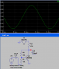
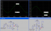
You forgot about Rin which is approx. Re*Hfe, or about 300 ohms. This is significant. I'll let you do the math, but below is the transistor amp and the equivalent circuit. The gain of both is 2.3 in simulation. With a 2N3904 in the same circuit, I also got a gain of 3.35. The higher beta lowers the collector voltage, increasing Ie and reducing Re. This increases Avol, which helps a little in this case, but Rin increases by a factor of 2 or more, which helps a lot.
 

Attachments

  • common emitter amp.PNG
    common emitter amp.PNG
    21 KB · Views: 440
Last edited:
That makes more sense now but where did you get 0.026 from?
 
Status
Not open for further replies.

Latest threads

New Articles From Microcontroller Tips

Back
Top