Continue to Site

Welcome to our site!

Electro Tech is an online community (with over 170,000 members) who enjoy talking about and building electronic circuits, projects and gadgets. To participate you need to register. Registration is free. Click here to register now.

  • Welcome to our site! Electro Tech is an online community (with over 170,000 members) who enjoy talking about and building electronic circuits, projects and gadgets. To participate you need to register. Registration is free. Click here to register now.

sinewave oscillator

Status
Not open for further replies.

metalbeard

New Member
Hello:
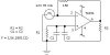
Am designing an FSK transmitter but in an old fashion way am using two sinewave oscillator (each on dependent frequency for 1s and 0s) which is wein bridge oscillator with an AGC as shown in the circuit below but the problem is that I couldn't know why is the grounding on the invert input of the op-amp and if it is correct how can I detrmine the gain of this op-amp.
As they are describing in the application note (that I got this circuit from) that the JFET serves as the AGC element, its gate voltage is zero when the power is applied leading to a low drain-to-source resistance (RDS). This places RG2+RS+RDS in parallel with RG1, raising the gain to 3.05, and as the output voltage grows, RDS increases, lowering the gain until the stabilization of the circuit which has the gain of 3
GAIN=(1+RF/( (RG2+RS+RDS)//RG1) ).
So I would be very happy if any one could help me finding the calculations of the gain of this circuit and how they got the 3.05 (assuming that RDS=zero when the power is applied).
(if the circuit doesn't appear click on the link)
http://www.geocities.com/metalbeard/index.html
**broken link removed**
 
When you are going to post an attachment, click the "Preview" button to see what is going to be posted.
I usually try to attach either .GIF or .JPG formats. I don't know if others work. I think most .BMP (bitmap) files are too big, and will be rejected.
 
I see you are looking at Ron Mancini's document about sinewave oscillators. Someone needs to tell him there's a schematic error. The inverting input is grounded, which won't work. If you remove that connection, it might work. Both source and drain will start out at 2.5v. With the gate starting at zero volts, the JFET will probably be slightly on, depending on threshold voltage. The general gain equation for a noninverting amplifier is

Av=1+(Rf/Rs), where Rf is from output to inverting input, and Rs is from inverting input to (AC) ground.

As you may have calculated, (Rg2+Rds+Rs)<79.13k for the gain to be greater than 3.05, where Rs in this case is the 10k resistor in the schematic.

See this treatise on sinewave oscillators for an alternate circuit (which I haven't tried). It describes how to linearize the JFET with two resistors so that distortion is minimized.
 
op-amp specifications

Hi...as I said before am designing an FSK transmitter and am using the wein bridge oscillator for that, I just want to know how can I decide which op-amp is the best for my application, I knew that I have to choose the op-amp depending on its bandwidth and the slew rate, but what is the slew rate?
So could any one help me finding the best op-amp for my application..... by the way the frequencies am using are 1.2KHz and 2.2KHz 8)
 
It depends somewhat on what power supply voltages you want to use, and what vendors you have access to. What voltage(s) are you planning on using? Are you still using the same circuit, without the spurious ground connection? What vendors can you buy from?
 
the power supply voltage is +12v and am using the circuit with AGC that is described in the treatise on sinewave oscillators you maintioned before, I haven't decided what vendors shall I select because I don't know what is the best op-amp that suits my application. I might use TL081 from Texas Instruments( what do u think about it? ).
 
metalbeard said:
the power supply voltage is +12v and am using the circuit with AGC that is described in the treatise on sinewave oscillators you maintioned before, I haven't decided what vendors shall I select because I don't know what is the best op-amp that suits my application. I might use TL081 from Texas Instruments( what do u think about it? ).

Any opamp will do, it's an extremely simple application, and only needs the lowest of specifications - a TL081 will be fine. If you like, fit a socket for the opamp (always a good idea anyway), and you can try different types and see if they make any difference.
 
I have used the attached circuit from below 500hz to over 20 Khz.
I have found that if you replace either R1 or R2 with a combination of a potentiometer and a fixed resistor equal to or near the value of R1 the frequency can be varied about 10%, and if both R1 and R2 are replaced
with a dual pot the variation in frequency to really great. The only disadvantages that I have found are that it requires a split supply and it takes a few cycles for the frequency to stabilize after changing frequency.
For a different lamp the 150 ohm resistor may need to be changed to ensure a sinewave.
 

Attachments

  • oscillator_700.jpg
    oscillator_700.jpg
    8.8 KB · Views: 630
I doubt that you can get the original circuit (without the erroneous GND connection) to work with a single supply. The output is biased at 2.5v, and has to swing negative far enough to cut off the JFET, which may require that the output swing below GND. I think changing Vref to 6 volts will solve that problem. The original circuit was apparently meant to run off a 5 volt supply, but it would still require a JFET with a cutoff voltage of less than 1.8 volts. With a 12 volt supply, that shouldn't be a problem.
 
Status
Not open for further replies.

Latest threads

New Articles From Microcontroller Tips

Back
Top