fezder
Well-Known Member
Hey, i decided to ask you pro's about his manner, as i couldnt verify is my knowledge right....but here goes:
I have this isolation transformer, which i wrote in blog little bit, but there are however couple things i need to ask before i start designing the case and so on. The issues are its safety lead, which is supposedly in center between primary and secondary, to prevent harm to user IF transformer gets impaled or otherwise damaged so mains is no longer isolated in addition to noise reduction, is this correct? And now there's this thing, i know that in order for safety-earth to work as intended, it needs to be connected in ''input'' mains, which is at the wall. But, what about the other side, secondary, which is used in test equipment? Is it needed in secondary side as there is isolation between earth and secondary live?. Also this transformer which i have has 2xmains in secondary, according to teacher they can be paralled as they are in same phase.
And as i mentioned in title, i have also question/s regarding variac. I have already pre-assembled two-variacs in parallel to increase current handling. What becomes of fuse/thermal overload-fuse, they should be connected in winding, right? but what about noise filter, as it seems to need that too, which i also have, does that go to right at the input of variac, or even before I-transformer?...Of course i'll add fuses in-line before I-transformer.
voltage and amperage meters go of course the output of the variac in series and parallel, as normal. I may sound that i have no clue whatsoever i'm doing, but hopefully you dont' ''throw me out of the class'' or something. Main purpose is to make this thing so it can be used ''safely'' as test gear.....as mains is never safe.
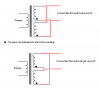
thanks for any assistance people") . I do have schematic if you want to check it out, but hopefully you understand what i'm after with this ''bomb''....
. I do have schematic if you want to check it out, but hopefully you understand what i'm after with this ''bomb''....
I have this isolation transformer, which i wrote in blog little bit, but there are however couple things i need to ask before i start designing the case and so on. The issues are its safety lead, which is supposedly in center between primary and secondary, to prevent harm to user IF transformer gets impaled or otherwise damaged so mains is no longer isolated in addition to noise reduction, is this correct? And now there's this thing, i know that in order for safety-earth to work as intended, it needs to be connected in ''input'' mains, which is at the wall. But, what about the other side, secondary, which is used in test equipment? Is it needed in secondary side as there is isolation between earth and secondary live?. Also this transformer which i have has 2xmains in secondary, according to teacher they can be paralled as they are in same phase.
And as i mentioned in title, i have also question/s regarding variac. I have already pre-assembled two-variacs in parallel to increase current handling. What becomes of fuse/thermal overload-fuse, they should be connected in winding, right? but what about noise filter, as it seems to need that too, which i also have, does that go to right at the input of variac, or even before I-transformer?...Of course i'll add fuses in-line before I-transformer.
voltage and amperage meters go of course the output of the variac in series and parallel, as normal. I may sound that i have no clue whatsoever i'm doing, but hopefully you dont' ''throw me out of the class'' or something. Main purpose is to make this thing so it can be used ''safely'' as test gear.....as mains is never safe.
thanks for any assistance people
. I do have schematic if you want to check it out, but hopefully you understand what i'm after with this ''bomb''....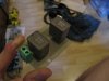
.jpg")
.jpg")
.jpg")
